Encoder interpolator with enhanced precision

Active Publication Date: 2010-12-02
ACTIVE PRECISION
View PDF31 Cites 39 Cited by
  • Summary
  • Abstract
  • Description
  • Claims
  • Application Information

AI Technical Summary

Benefits of technology

[0024]The state estimator allows a high resolution interpolation to be achieved without compromising speed. The resolution of the interpolator is determined by the resolution of the analog to digital converter (ADC) used to digitize the raw encoder signals as well as the ratio between the sample rate of the state estimator and the bandwidth of the state estimator. With typical “over sampling ratios” of 50,000:1 (10 MHz/2 kHz), there is approximately a 70 fold (square root of 50,000) increase in resolution at the output of the interpolator compared to the resolution of the ADC.

Problems solved by technology

The bandwidth limited output of the state estimator attenuates high frequency noise and er

Method used


Image

  • Encoder interpolator with enhanced precision
  • Encoder interpolator with enhanced precision
  • Encoder interpolator with enhanced precision

Examples


Example

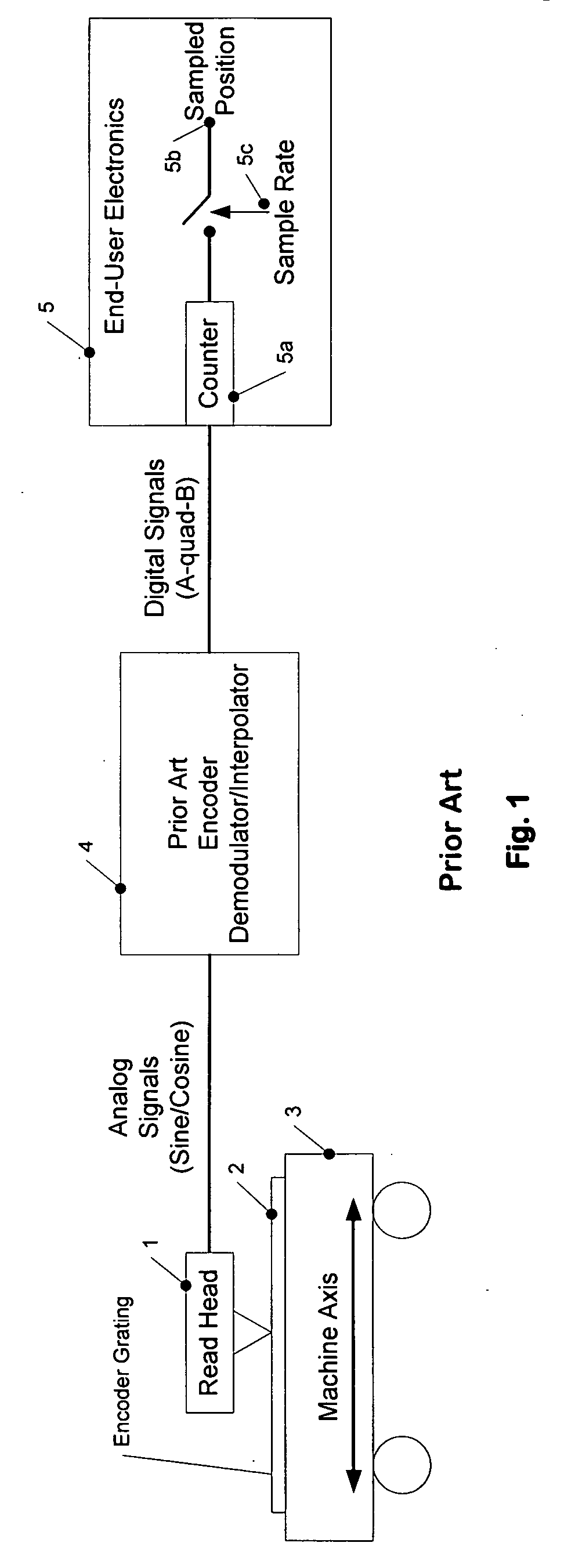
[0042]FIG. 1 is a block diagram of a system that incorporates an analog encoder consisting of read head 1 and grating 2 mounted on machine axis 3, prior art encoder demodulator / interpolator 4 and end-user electronics 5. The end-user electronics 5 includes a counter 5a that counts the digital pulses produced by the encoder interpolator 4. The counter output is sampled at a fixed rate 5c to produce a sampled position signal 5b that is used by the end-user electronics.

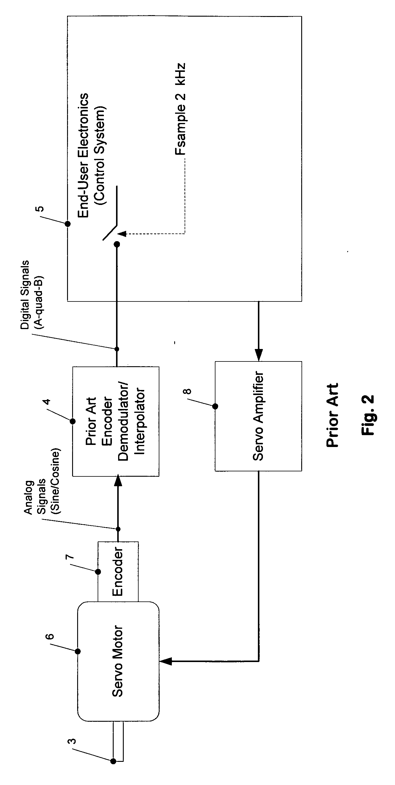
[0043]FIG. 2 is a block diagram of a machine control system that includes similar elements as shown in FIG. 1. The end-user electronics 5 implements a control system to control a servo motor 6 that is connected to a machine axis 3. A rotary encoder 7 attached to the motor provides analog signals to a prior art encoder demodulator / interpolator 4. The digital signals from the interpolator are sampled by the end-user electronics 5 at a fixed sample rate.

[0044]FIG. 3 is a block diagram of a prior art demodulator / interpolator....


PUM


Abstract

A method is presented for converting the sine/cosine signals from an optical encoder into a high-resolution position signal for use by a position control system while eliminating common noise and error sources. The improved noise performance resulting from the alias-free demodulation of encoder signals improves precision and reduces power consumption in precision motion control applications. The adaptive compensation of harmonic distortion eliminates errors related to offset, gain and quadrature of the encoder channels. The interpolator is able to process encoder signals at extremely high resolution without the speed limitation of prior art encoder interpolators.

Description

RELATED APPLICATIONS[0001]This application claims priority to U.S. Provisional App. No. 61 / 217,121, filed May 27, 2009, which is incorporated herein by reference.TECHNICAL FIELD[0002]This application is directed to the field of encoders and, more particularly, to an encoder interpolator with enhanced precision.BACKGROUND OF THE INVENTION[0003]Optical encoders are widely used for measuring the position of machine elements. They are commercially available in a range of configurations for measuring either rotary or linear motion. This invention relates to the subset of encoders that produce incremental analog output signals in quadrature. These are typically referred to as “1 volt peak-peak” or simply “analog” encoders. An alternate encoder format, commonly called “A-quad-B”, produces a digital data stream rather than the analog voltage signals of analog encoders.[0004]In reality, all high-resolution “digital” encoders are in fact analog encoders equipped with demodulators (or interpol...

Claims


Application Information

Patent Timeline
IPC IPC(8): H04B17/00
CPCG01D5/24419G01D5/24495
Inventor HUNTER, BRADLEY
Owner ACTIVE PRECISION
Why Eureka
Try Eureka