Fluid dynamic section having escapelet openings for reducing induced and interference drag, and energizing stagnant flow

Inactive Publication Date: 2010-12-02
LONG DONALD JAMES
View PDF54 Cites 52 Cited by
  • Summary
  • Abstract
  • Description
  • Claims
  • Application Information

AI Technical Summary

Benefits of technology

[0012]The fluid dynamic structures encompassed by this improvement may include not only aircraft wings, but also aircraft control surfaces, such as ailerons, flaps, aircraft empennages, canards, including stabilizers, elevators, fins, rudders, together with rotor blades, propeller blades, turbofans, ducted fans, and wind tunnel drive fans, as found on both helicopters and wind-power turbines, as well as foil bodies on various watercraft, i

Problems solved by technology

Another problem in aircraft design is the production of trailing vortices and wake turbulence during flight.
Wingtip vortices have been considered by many experts to be an essentially unavoidable consequence of a wing producing lift.
Due to the nature of these vortices, they are associated with lift-induced drag and are a major component of wake turbulence.
The drag and wake turbulence from the vortices have a negative impact on fuel efficiency and flight performance of the aircraft, and also pose a safety hazard to any aircraft that follow too closely or otherwise cross the wake.
Since wingtip vortices only affect that portion of a wing closest to its tip, one partial solution is to use a higher aspect ratio wing (longer wingspan and/or reduced chord), but this

Method used


Image

  • Fluid dynamic section having escapelet openings for reducing induced and interference drag, and energizing stagnant flow
  • Fluid dynamic section having escapelet openings for reducing induced and interference drag, and energizing stagnant flow
  • Fluid dynamic section having escapelet openings for reducing induced and interference drag, and energizing stagnant flow

Examples


Example

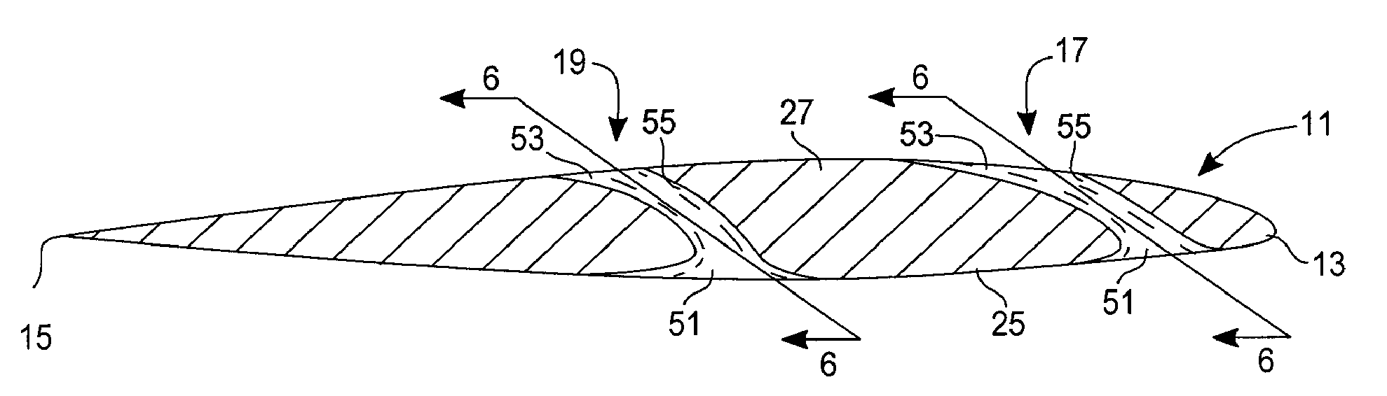
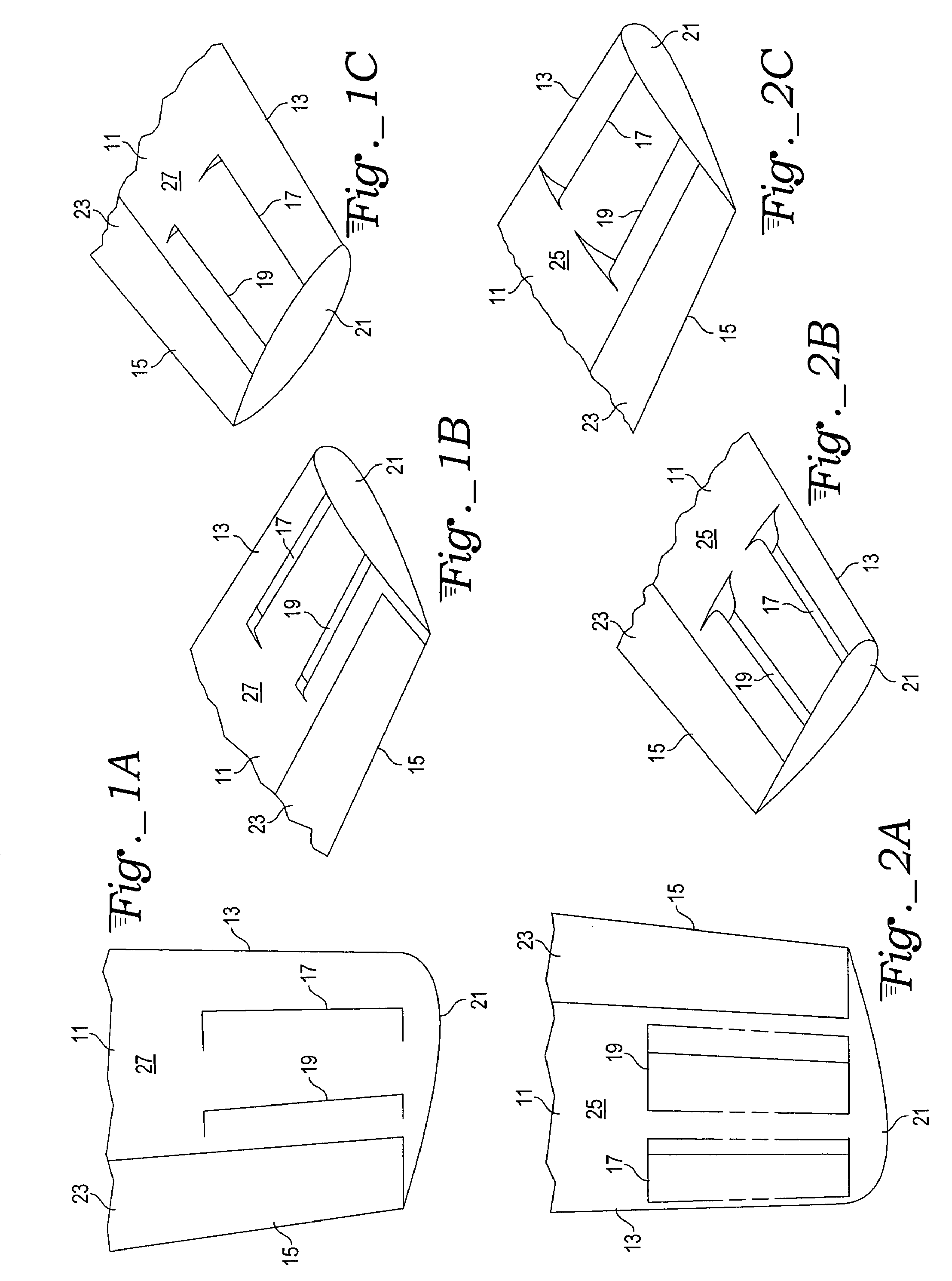
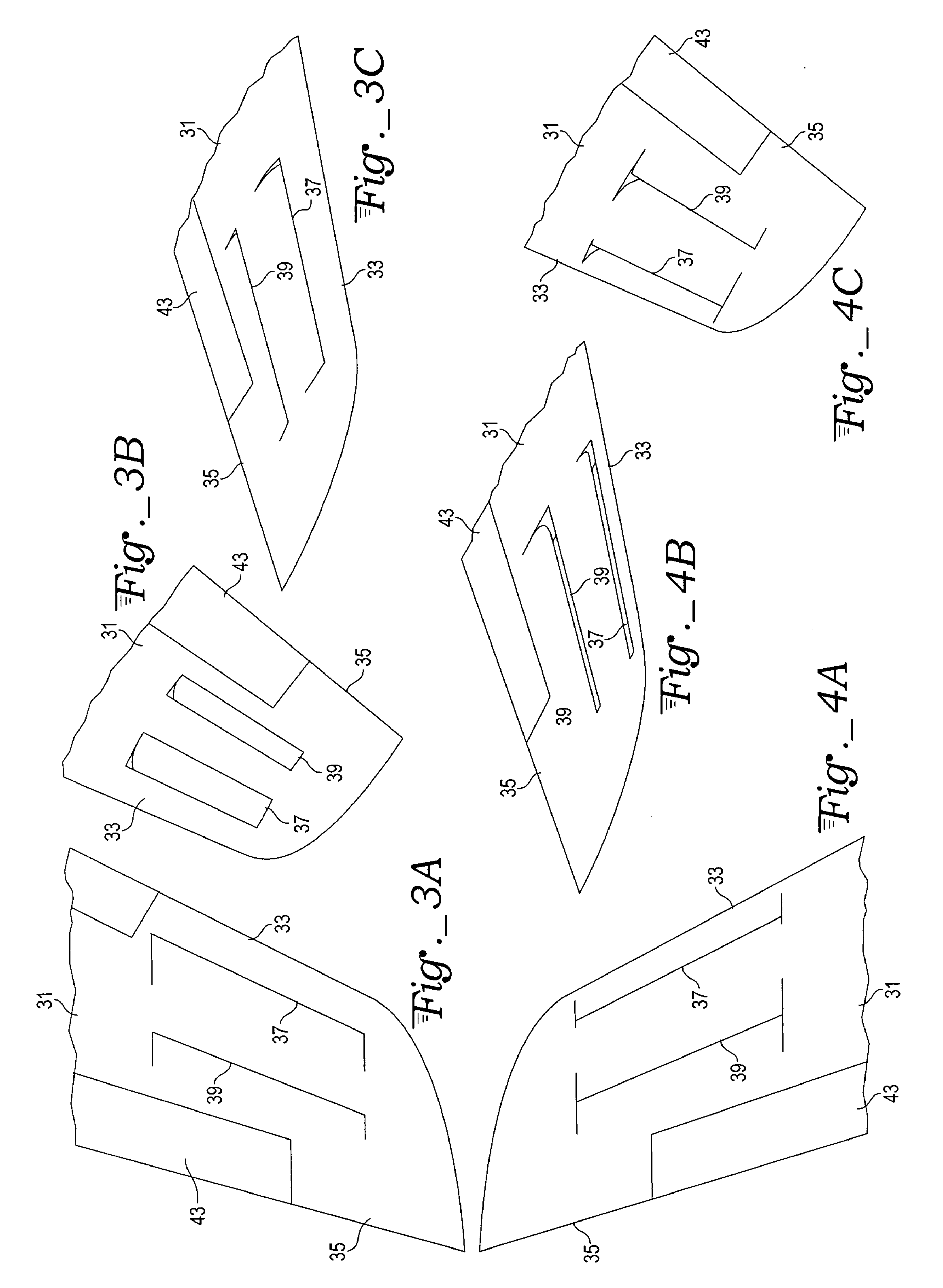
[0032]In order to better understand the improvements, we note first that slots, slats and slotted flaps have the purpose of increasing the maximum lift coefficient, thereby reducing the stall speed, while the escapelets provided within the various fluid dynamic sections in accord with the present invention have instead the purpose of preemptively redirecting fluid flow energy before it can cause fluid dynamic havoc manifesting as vortices, turbulence, wake and drag with consequent wasteful energy dissipation. The escapelets harness, redirect and release the energy beneficially so as to minimize such energy losses. In addition to the benefits already discussed, escapelets may also be employed to reduce turbulence due to flow separation, thus making the associated flows more efficient.

[0033]“slot” (noun)—a long and narrow opening as between a wing and a Fowler flap; specif. a long and narrow spanwise passage in a wing usually near the leading edge for improving flow conditions at high...


PUM


Abstract

A fluid dynamic section provides one or more fixed size escapelets through a foil body to reduce the induced and interference drag caused by trailing vortices and similar wake turbulence. The escapelets, which can be provided in both aerodynamic and hydrodynamic structures, such as wings, tail sections; rotary blades, guy wire frames, wing sails, and various underwater keels and wing keels. The escapelets transfer energy from an inlet located in the high-pressure surface of the foil or foil body to an outlet located in the lower-pressure surface, allowing energy that would normally form a vortex at the tip of the foil to be redirected and dissipated in a beneficial way. As a result, drag is reduced and fuel economy is increased, while at the same time increasing the authority of ailerons and similar flight control surfaces, allowing aircraft that were not previously spin recovery rated to become spin recoverable.

Description

TECHNICAL FIELD[0001]The present invention relates to improvements to foils and related fluid dynamic structures for influencing or controlling aerodynamic or hydrodynamic flows to reduce drag, such as drag and turbulence induced by wingtip vortices of an aircraft, cooling and ventilating drags, or such as is found in the wake of a watercraft. The invention also relates to slot-like structures for fluid dynamic foil bodies.BACKGROUND ART[0002]Slots have been used for years in many aircraft wing designs in order to prevent the airflow from separating prematurely from the wing at high angles of attack, and thereby reduce the stall speed and improve handling at low speeds. Air from below the wing accelerates through the slot and exits rearward and substantially parallel to the upper wing surface, energizing the boundary layer and delaying separation. A similar approach provides a pressurized discharge from wing surface openings, either from compressed air tanks, pumps, or from the jet ...

Claims


Application Information

Patent Timeline
IPC IPC(8): B64C11/20F01P1/00
CPCB63B1/248B63B3/38B63B35/7926B63B39/06B63B41/00B63H9/0607B63H25/38B64C21/02B64D33/08F01D5/146F01P1/02F01P5/06F04D29/324F04D29/38F04D29/681F15D1/10Y02T50/166Y02T50/671Y02T50/673Y02T70/583Y02T70/14B63H9/061Y02T50/10Y02T50/60Y02T70/10Y02T70/5236F04D29/682F04D29/684
Inventor LONG, DONALD JAMES
Owner LONG DONALD JAMES
Why Eureka
Try Eureka