Microwave Ablation Safety Pad, Microwave Safety Pad System and Method of Use

a technology of safety pads and safety pads, which is applied in the field of systems, apparatus and methods for performing medical procedures, can solve problems such as undesirable complications, potential risk of percutaneous insertion, and overshooting of percutaneous devices into adjacent areas

Active Publication Date: 2010-12-02
TYCO HEALTHCARE GRP LP
View PDF38 Cites 57 Cited by
  • Summary
  • Abstract
  • Description
  • Claims
  • Application Information

AI Technical Summary

Benefits of technology

[0014]In yet another embodiment, a microwave ablation safety pad system includes a microwave generator capable of generating a microwave frequency signal, a microwave ablation device and a microwave ablation safety pad. The microwave ablation device includes a microwave antenna configured to resonate and deliver microwave energy to a target tissue. The microwave ablation safety pad is configured to prevent thermal energy generated in the tissue target from conducting to a healthy tissue, to prevent the emanation of electrosurgical fields to healthy tissue and to prevent the microwave ablation device from physically contacting healthy tissue.

Problems solved by technology

One potential risk of percutaneous insertion occurs when the clinician inserting the percutaneous device overshoots the target tissue and the tip of the percutaneous device makes physical contact with tissue adjacent the target tissue.
The risk of overshoot of a percutaneous device into adjacent tissue becomes particularly relevant when the adjacent tissue is susceptible to damage.
For example, accidental insertion into a member of the vascular system (i.e., a vein, artery and / or heart), a portion of the respiratory system (i.e., lung) and / or a portion of the digestive system (i.e., esophagus and / or stomach) may lead to undesirable complications.
Multiple insertions of microwave energy delivery device with a system array or repeated insertions for particular procedures may further exasperate the potential risk, e.g., an organ resection procedure where a plurality of devices are inserted along a resection line in order to facilitate the removal of a portion of the organ.
In many procedures, the target tissue is often adjacent a portion of healthy tissue wherein thermal heating and electrical interference from the electromagnetic fields generated by the microwave antenna may unnecessarily transfer additional heat or energy outside a desired target area.

Method used


Image

  • Microwave Ablation Safety Pad, Microwave Safety Pad System and Method of Use
  • Microwave Ablation Safety Pad, Microwave Safety Pad System and Method of Use
  • Microwave Ablation Safety Pad, Microwave Safety Pad System and Method of Use

Examples


Embodiment Construction

[0019]Detailed embodiments of the present disclosure are described herein; however, it is to be understood that the disclosed embodiments are merely exemplary and may be embodied in various forms. Therefore, specific structural and functional details disclosed herein are not to be interpreted as limiting, but merely as a basis for the claims and as a representative basis for teaching one skilled in the art to variously employ the present disclosure in virtually any appropriately detailed structure.

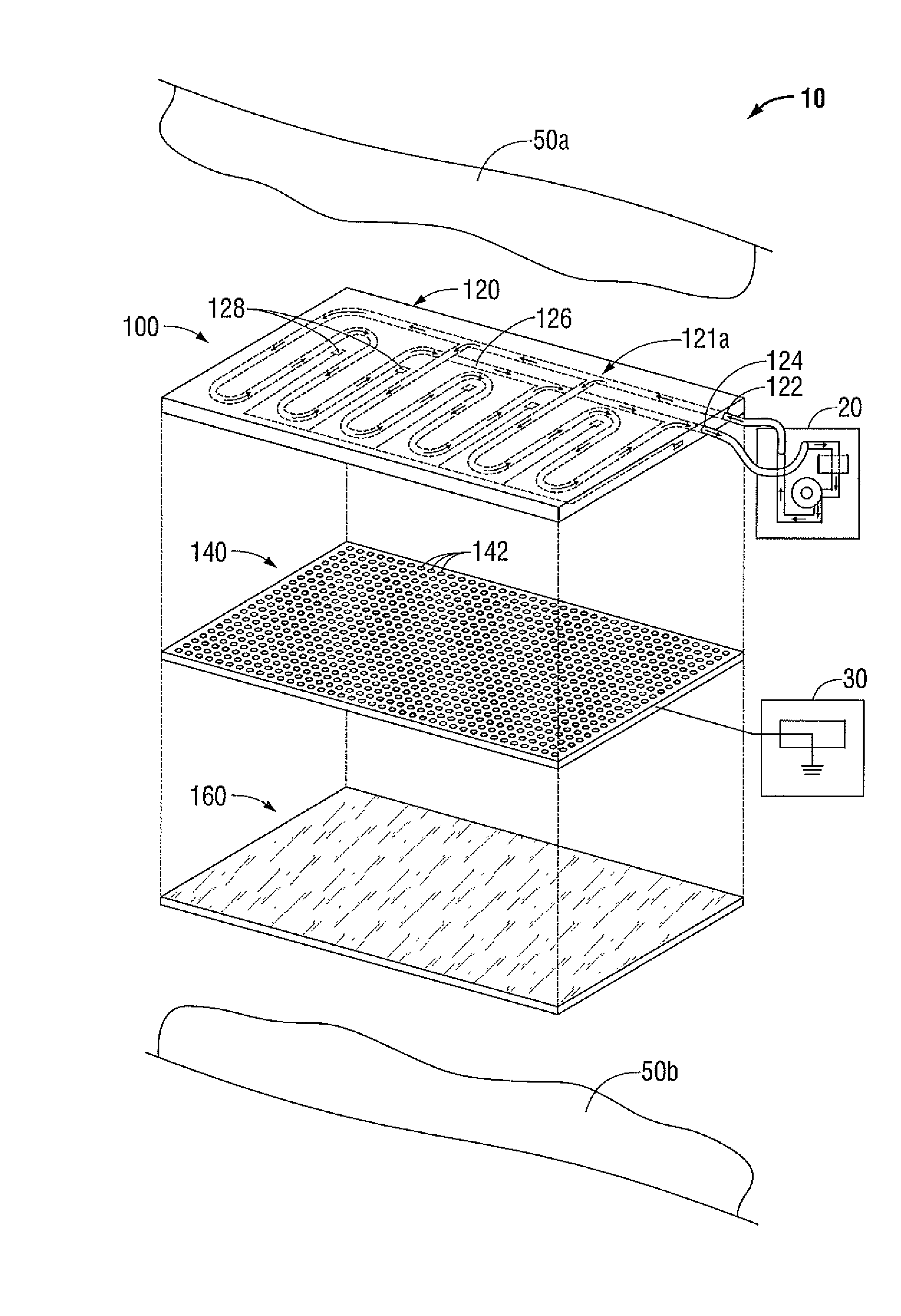
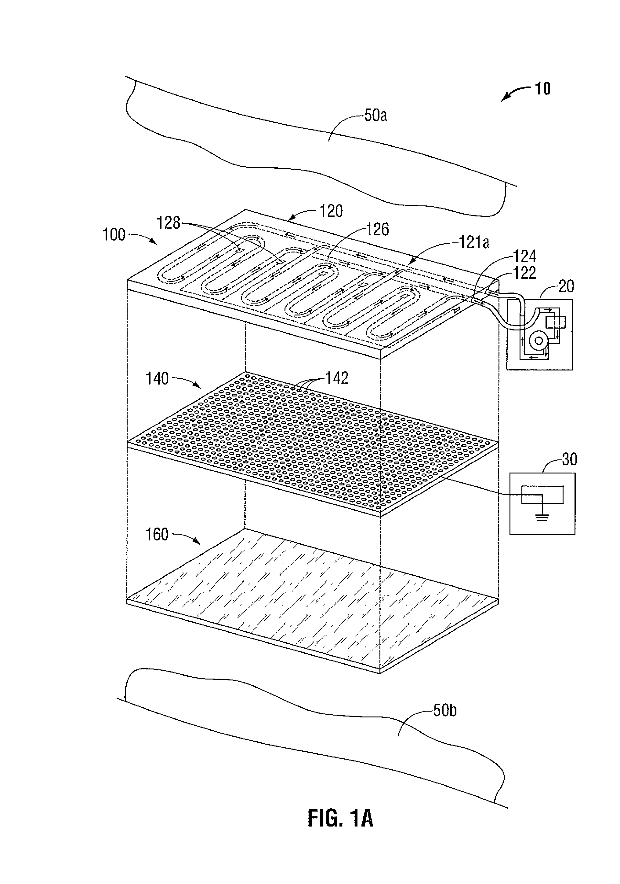
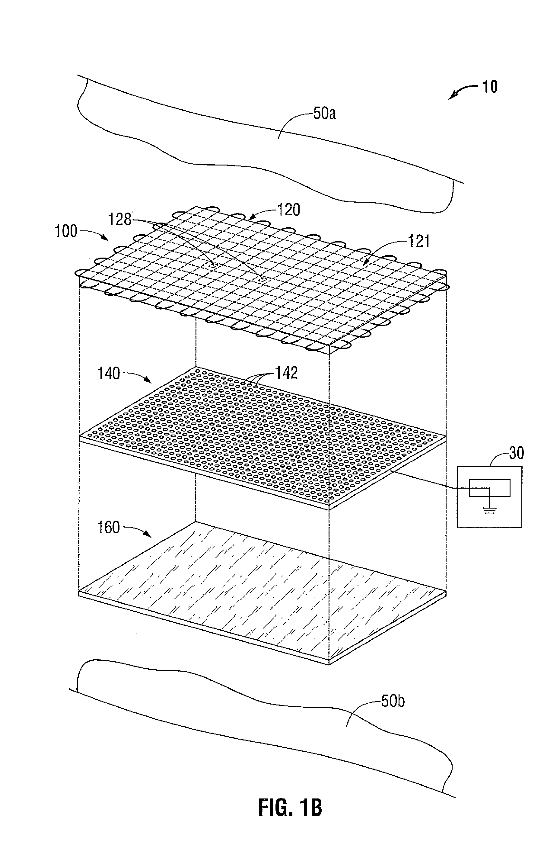
[0020]Referring to FIG. 1A, a microwave ablation safety pad system employing a microwave ablation safety pad 100a is generally designated as safety pad system 10a. Safety pad system 10a includes a microwave ablation safety pad 100a, a cooling fluid supply 20 and a grounding device 300. Safety pad system 10 may include individual components, as illustrated in FIG. 1, or the functionality of the individual components may be combined and / or consolidated in one or more components. Components a...


PUM


Abstract

A microwave ablation safety pad includes a base layer, an electromagnetic shielding layer and a physical protection layer. The base layer is configured to support a cooling medium designed to absorb thermal energy. The electromagnetic shielding layer, adjacent the base layer, includes a faraday shield configured to prevent the generation of electromagnetic fields. The physical protection layer, adjacent the electromagnetic shielding layer, is configured to resist penetration therethrough.

Description

BACKGROUND[0001]1. Technical Field[0002]The present disclosure relates to systems, apparatus and methods for performing a medical procedure, wherein a microwave ablation safety pad is used to protect a healthy portion of body tissue during a microwave ablation procedure. More particularly, the present disclosure relates to a microwave ablation safety pad configured to protect the healthy portion of body tissue during the insertion of a tissue penetrating energy delivery device into a target tissue, during the delivery of microwave energy to the target tissue and from a cutting device used during a subsequent resection of the target tissue. Embodiments of a microwave ablation safety pad in accordance with the present disclosure provide a plurality of protective layers to protect a healthy portion of body tissue from the possible effects of physical, thermal and / or electrical contact from a microwave energy delivery device and / or a resection device.[0003]2. Description of Related Art[...

Claims


Application Information

Patent Timeline
Patent Type & Authority Applications(United States)
IPC IPC(8): A61B18/18
CPCA61B2018/00023A61B2090/0481A61B2090/0436A61B90/04
Inventor PETERSON, DARION
Owner TYCO HEALTHCARE GRP LP
Why Eureka
Try Eureka