Permanent Magnet Motion Amplified Motor and Control System

a permanent magnet and amplified motor technology, applied in the field of magnetomotors, can solve the problems of increasing the weight of the rotor, the weight of the portion corresponding to the rotary assembly section becomes heavy, and the conventional power transmission mechanism for transmitting drive power from a power source to the wheels in a typical internal combustion piston engine cannot generally be applied to electric vehicles, so as to achieve the effect of enhancing the output power of the rotary motor

Inactive Publication Date: 2010-12-09
WARDENCLYFFE TECH
View PDF0 Cites 26 Cited by
  • Summary
  • Abstract
  • Description
  • Claims
  • Application Information

AI Technical Summary

Benefits of technology

[0011]Also provided is a rotary motor comprising a rotor having a plurality of rotor magnets mounted thereon, each rotor magnet having a first magnetic pole and a second magnetic pole. The rotary motor further includes a stator adjacent to the rotor comprising a stator magnet and a stator motor, the stator magnet having a first magnetic pole that is the same polarity as the first magnetic pole of the rotor magnets, and a second magnetic pole that is the same polarity as the second magnetic pole of the rotor magnets. In this embodiment, the stator motor drives the st...

Problems solved by technology

The electric drive motors of such a type, however, lead naturally to an increase in the weight of a rotor in order to generate a greater output and, as a consequence, suffer from the disadvantages that the weight of the portion corresponding to a rotary assembly section becomes heavy.
In addition, conventional power transmission mechanisms for transmitting drive power from a power source to the wheels in a typical internal combustion piston engine...

Method used


Image

  • Permanent Magnet Motion Amplified Motor and Control System
  • Permanent Magnet Motion Amplified Motor and Control System
  • Permanent Magnet Motion Amplified Motor and Control System

Examples


first embodiment

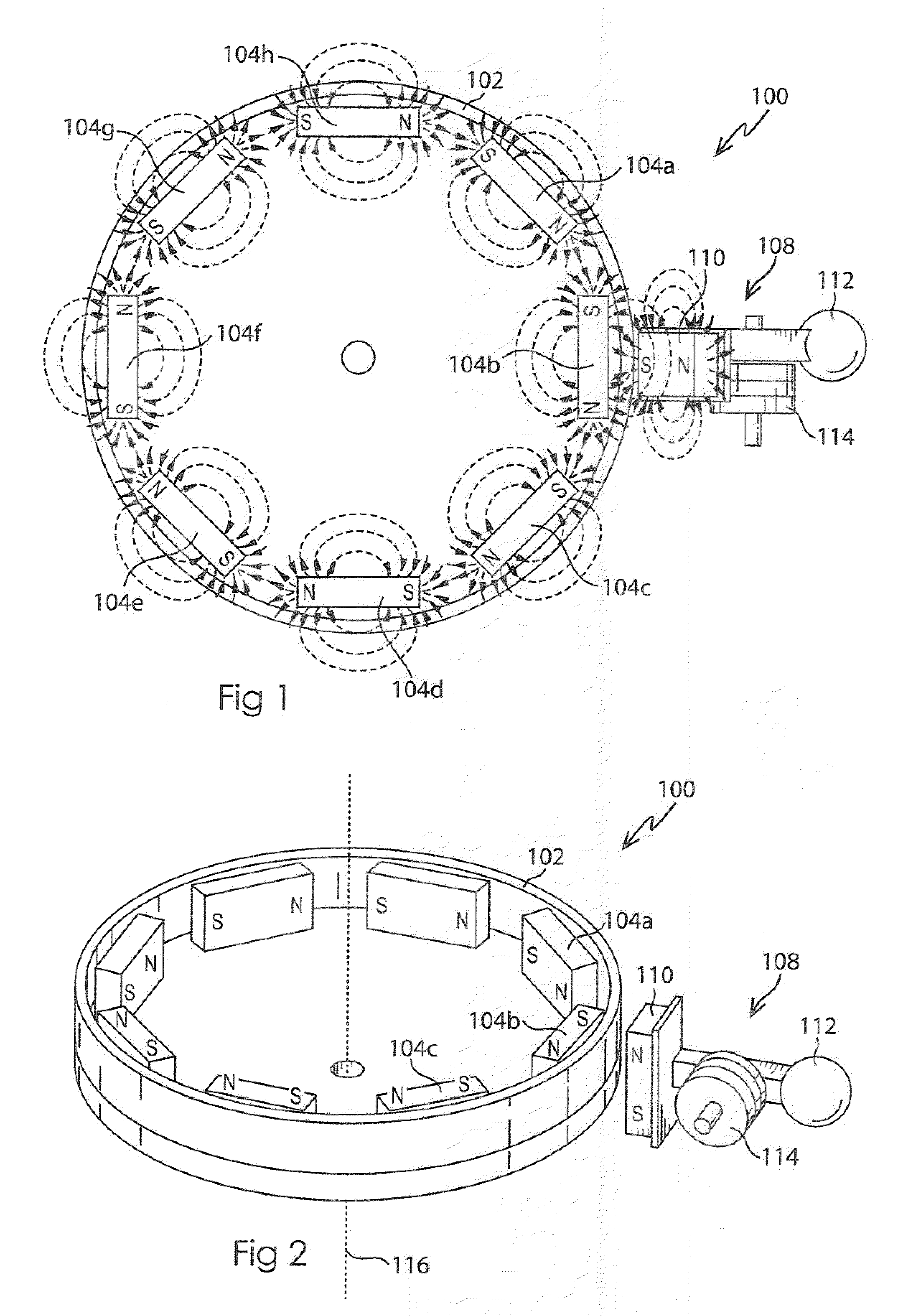
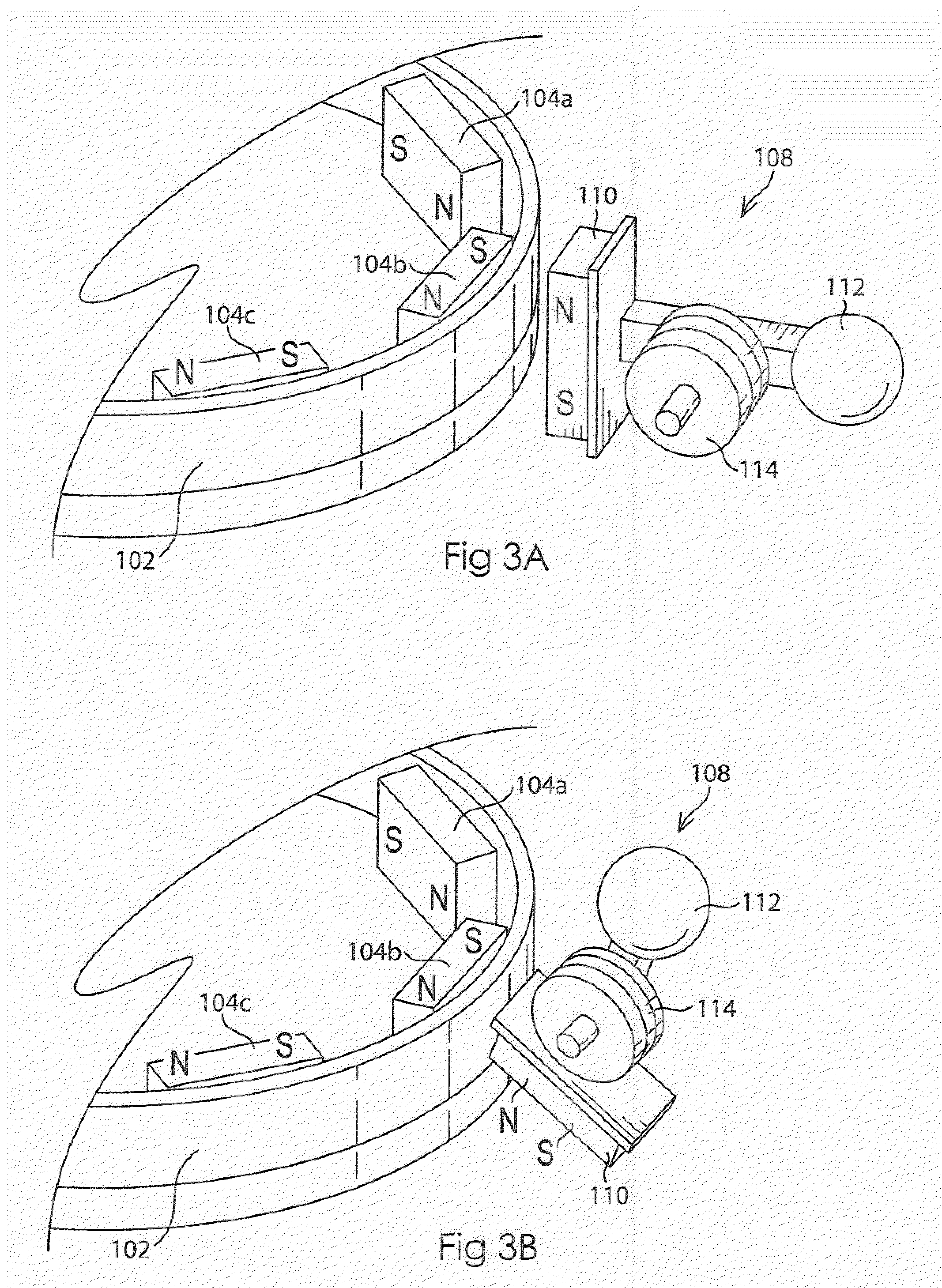
[0042]FIG. 1 illustrates a top view of a permanent magnet rotary motor 100 in accordance with the invention, and FIG. 2 is a perspective view of the permanent magnet rotary motor of FIG. 1. The permanent magnet rotary motor 100 of FIG. 1 includes a rotor 102 having a plurality of rotor magnets 104 mounted along the inside of the rotor 102. While the embodiment illustrated in FIG. 1 includes eight rotor magnets 104a-h, one of ordinary skill in the art having the present drawings, specifications, and claims before them would understand that more or fewer rotor magnets may be used. The motor 100 further includes an oscillating stator 108 adjacent the rotor 102 at its periphery. While the embodiment illustrated in FIG. 1 uses an oscillating stator, as would be understood by one of skill in the art having the present drawings, specifications, and claims before them, other types of stators may be used. For example, as described in further detail below with respect to FIGS. 4-6, a rotating...

second embodiment

[0046]FIG. 4 is a top view of a permanent magnet rotary motor 200 in accordance with the invention, and FIG. 5 is a perspective view of the permanent magnet rotary motor of FIG. 4. The permanent magnet rotary motor 200 illustrated in FIGS. 4 and 5 is similar to that of FIGS. 1 and 2, however it uses a different type of stator 208. The stator 208 of FIGS. 4-5 is a rotating stator 208 which includes a cylindrical stator magnet 210 and a stepper motor 114. The cylindrical stator magnet 210 is preferably diametrically magnetized such that half of the cylindrical stator magnet 210 divided along a diameter corresponds to the north pole (N) of the magnet, and the other half of the cylindrical stator 208 corresponds to the south pole (S).

[0047]As previously explained, the rotor 102 is adjacent to the stator 208 such that when the respective magnetic fields of the rotor magnet(s) 104b adjacent the stator 208 interact with the magnetic field of the stator magnet 210, as the stator magnet 208 ...

third embodiment

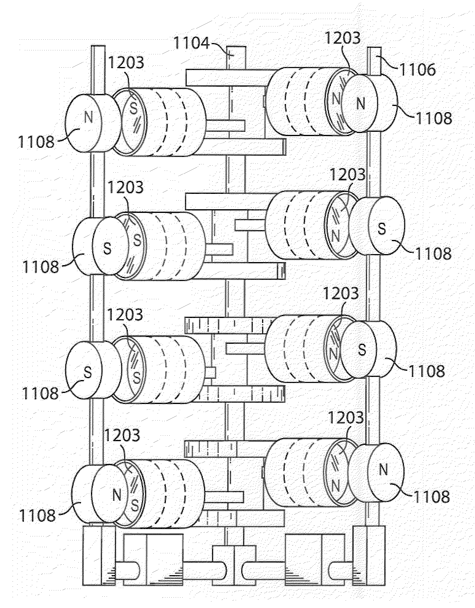
[0050]FIG. 7 is a top view of a permanent magnet rotary motor 700 in accordance with the invention. The embodiment of FIG. 7 illustrates a single rotor similar to the rotor 102 of FIG. 1, with a plurality of oscillating stators 108 (referred to as a multi-unit stator 750), rather than a single stator as in FIG. 1. While FIG. 7 illustrates eight stators 108 evenly spaced, one of skill in the art having the present drawings, specifications, and claims before them would understand that any number of stators may be used, and the placement around the rotor need not necessarily be evenly spaced as shown. One of skill in the art having the present specification before them would also understand that different types of stators, such as the rotating stator 208 of FIGS. 4-5, may be used instead of, or in addition to, the oscillating stators 108 in a multi-unit stator 750. The additional stators increase the power output of the motor. FIG. 8 is a perspective view of the permanent magnet rotary...


PUM


Abstract

A permanent magnet motor operated by the magnetic interaction between two or more permanent magnets, and a control system therefor, is provided. The permanent magnet motor may be a piston motor having a magnetic piston assembly mounted on a crank shaft, and a rotatable cam shaft having a cam magnet corresponding to the piston assembly. When the cam shaft rotates about an axis, the poles of the cam magnet alternatingly face the adjacent magnetic pole of the corresponding piston magnet. The magnetic field interactions between the piston magnet and the cam magnet cause the piston to reciprocate within the cylinder. The permanent magnet motor may also be a rotary motor comprising a rotor having a plurality of rotor magnets, and a stator having a stator magnet. A stator motor drives the stator causing the rotor to rotate in response to alternating interactions between magnetic fields of the stator magnet and rotor magnets. A vehicle comprising a permanent magnet motor is also disclosed.

Description

BACKGROUND OF THE INVENTION[0001]1. Field of the Invention[0002]The present invention relates to magnetic motors, and in particular to a permanent magnet motor operated by the magnetic interaction between two or more permanent magnets, and a control system therefor.[0003]2. Background Information[0004]In recent years, the development of electric vehicles is exploding. Such electric vehicles use an electric drive motor as a power source. Conventional electric drive motors are designed to generate power by directly rotating a rotor by electromagnetic force from batteries or other electrical input.[0005]The electric drive motors of such a type, however, lead naturally to an increase in the weight of a rotor in order to generate a greater output and, as a consequence, suffer from the disadvantages that the weight of the portion corresponding to a rotary assembly section becomes heavy. This is also true of their power supplies. In addition, conventional power transmission mechanisms for ...

Claims


Application Information

Patent Timeline
IPC IPC(8): H02K7/18H02K21/02H02K7/09B60K8/00H02N11/00
CPCH02K53/00
Inventor WALDEN, MICHAEL K.
Owner WARDENCLYFFE TECH
Why Eureka
Try Eureka