Efficient solid fuel burning appliance

a solid fuel and efficient technology, applied in the combustion process, chamber doors, lighting and heating apparatus, etc., can solve the problems of rising petroleum fuel costs, staggering effects, lack of efficiency, etc., and achieve the effect of more efficient heat distribution and more economical construction

Active Publication Date: 2010-12-16
MURRAY ANDREW
View PDF26 Cites 5 Cited by
  • Summary
  • Abstract
  • Description
  • Claims
  • Application Information

AI Technical Summary

Benefits of technology

[0010]The present invention is a device for burning wood or other solid fue

Problems solved by technology

Many of the reasons for the increase include rising petroleum fuel costs, the availability of wood and alternative fuels, and the staggering effects mining, drilling, processing, transporting and the burning of fossil fuels have on the environment.
A problem with existing wood-based and other solid fuel burning appliances, however, is their lack of efficiency.
That is, they are inefficient in many ways.
Moreover, existing wood-based and other solid fuel devices generally tend not to burn their fuel as completely as petroleum fueled furnaces and a significant amount of heat escapes directly out the flue.
The, e.g., rectangular or square, sha

Method used


Image

  • Efficient solid fuel burning appliance
  • Efficient solid fuel burning appliance
  • Efficient solid fuel burning appliance

Examples


Embodiment Construction

[0064]Preferred embodiments of the invention will now be described, by way of example only and not to limit the invention, with reference to the accompanying drawings.

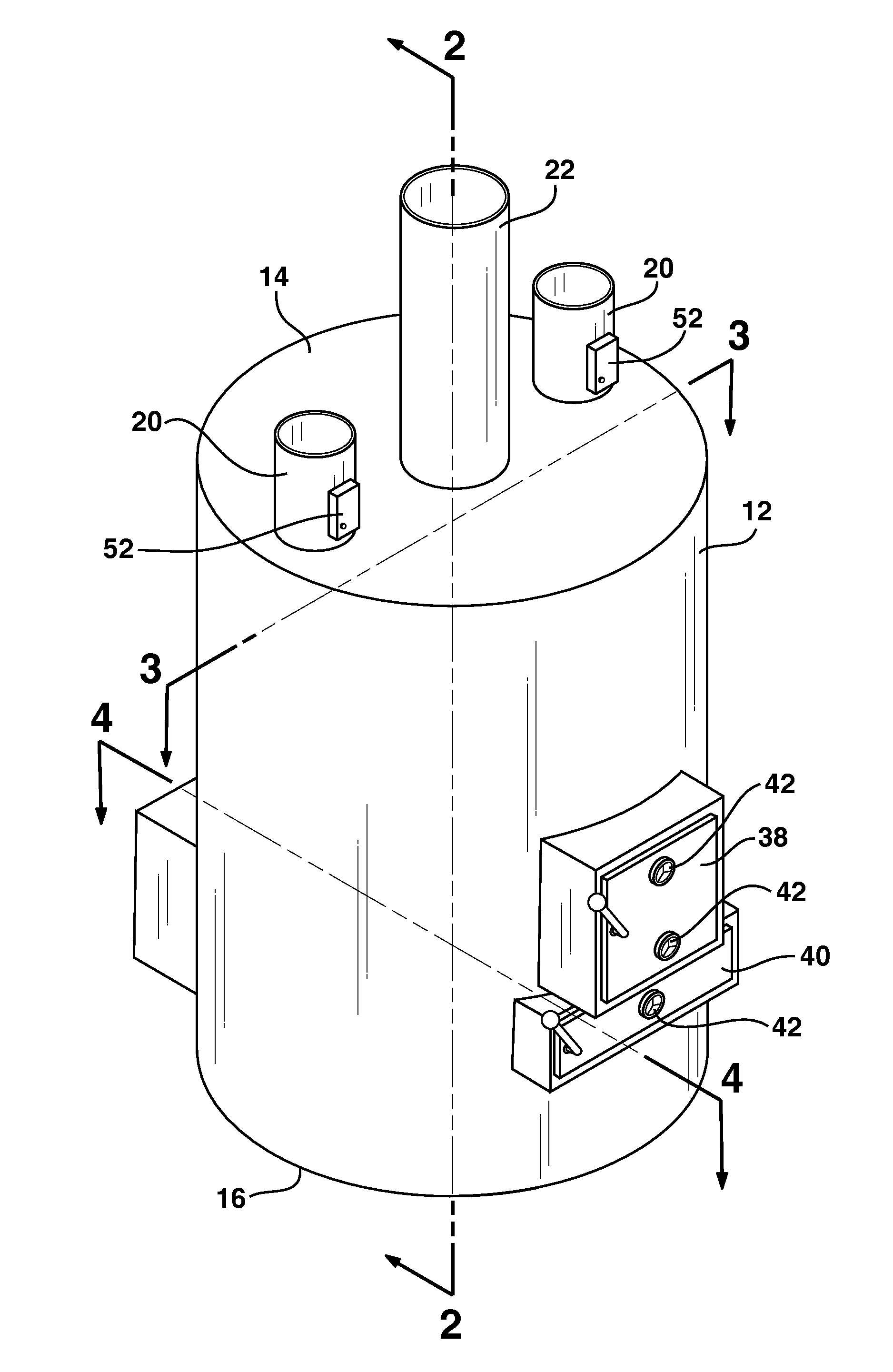
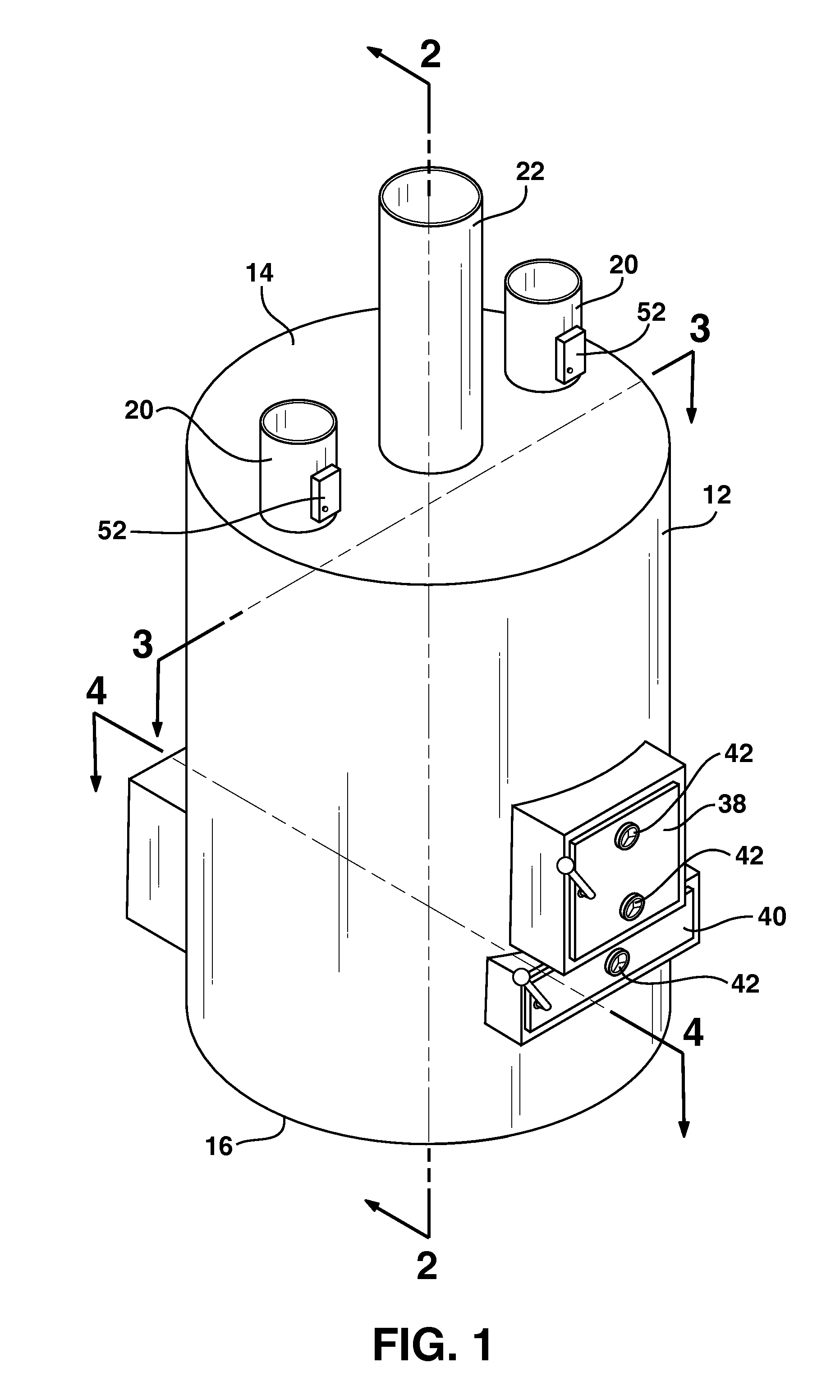
[0065]FIG. 1 is a perspective view of an appliance for burning solid fuels according to at least one embodiment of the appliances disclosed herein. The appliance, e.g., a furnace, boiler, etc., is comprised of an outer shell 12, an outside bottom 16 and outside top 14. The outer shell 12 is a vertical cylinder in the preferred embodiment. General construction of the appliance is from A36 mild sheet steel or any other material suitable for this means. The material may be joined by welding or by any other method suitable for joining the construction material. Protruding from the outside top 14 of the appliance is a flue 22 and one or more ducts 20. Protruding from the back of the outside shell 12 is a housing containing one or more blowers / pump 48, controlled by one or more fan limit switches 52. Protruding from the fron...


PUM


Abstract

A wood or other bio mass fueled appliance is disclosed for maximum efficiency and low cost construction for home, garage, workshop, and barn. Comprised of a vertical cylindrical outside shell (12) outside bottom (16) and outside top (14) enclosing an inside shell (24) inside bottom (28) and inside top (26). Inside shell (24) forming a vertical cylindrical chamber (36) accessed by load door (38) and ash door (40), through which disassembled baffles (32) may pass. A suitable means for igniting fuel in chamber (36) and controlling burn rate by draft regulators (42) and fan limit switches (52). Whereby circular baffles (32) elevated by 90° angle shaped supports (30) suppress the flow of flame and exhaust gases from entering flue (22). Exhaust gases and flame pass by gap (50), directing energy toward the inside surface of inside shell (24) inside bottom (28) and inside top (26). Thus maximizing the efficiency of heat transferred from chamber (36) to the air or fluid in space (18) circulated through ducts (20) by blowers/pumps (48) and directed by air deflectors (46) producing economizing results.

Description

[0001]This application claims priority to U.S. Provisional Application No. 61 / 268,232, filed Jun. 10, 2009, which is hereby incorporated herein by reference.BACKGROUND OF THE INVENTION[0002]This application relates generally to an appliance for burning solid fuels, such as wood, corn, pellets, etc., and more specifically for better combustion, more efficient heat distribution, and more economical construction.[0003]With the increased price of energy, especially the fossil fuels, interest in alternative energy sources, mainly wood derived, to heat the interior space of any structure needing a rise in temperature has grown significantly over the past years, largely by moderate income families trying to reduce the bite of inflation, but also by a sizable segment of low income families who simply cannot afford fossil derived fuels.[0004]Wood-burning devices have been well known for a long time, however, their popularity fluctuates. When petroleum fuel is readily available and reasonably...

Claims


Application Information

Patent Timeline
IPC IPC(8): F23K3/00F23M7/00F23H17/00
CPCF23B60/02F23B80/04F23M11/042F23L17/00F23M7/00F23L13/00
Inventor MURRAY, ANDREW
Owner MURRAY ANDREW
Why Eureka
Try Eureka