Computer graphic generation and display method and system

a computer graphic and display method technology, applied in the field of computer graphic generation and display methods, can solve the problems of special imaging devices, complex conventional procedures for building and/or deforming such graphic models, and it is impractical for ordinary people with ordinary cameras to use such procedures

Inactive Publication Date: 2010-12-16
CAI TAO
View PDF10 Cites 43 Cited by
  • Summary
  • Abstract
  • Description
  • Claims
  • Application Information

AI Technical Summary

Benefits of technology

[0012]One aspect of the present disclosure includes a computer-implemented method for generating and transforming graphics related to an object for a user. The method includes obtaining one or more images taken from different points of view of the object, and a surface of the object is placed with a plurality of external markers such that control points for image processing are marked by the external markers. The method also includes building a spatial model from the one or more images based on the external markers, and processing the one or more images to restore original color of parts of the one or more images covered by the external markers. Further, the method includes integrating texture from the restored images with the spatial model to build an integrated graphic model, and saving the integrated graphic model in a database.

Problems solved by technology
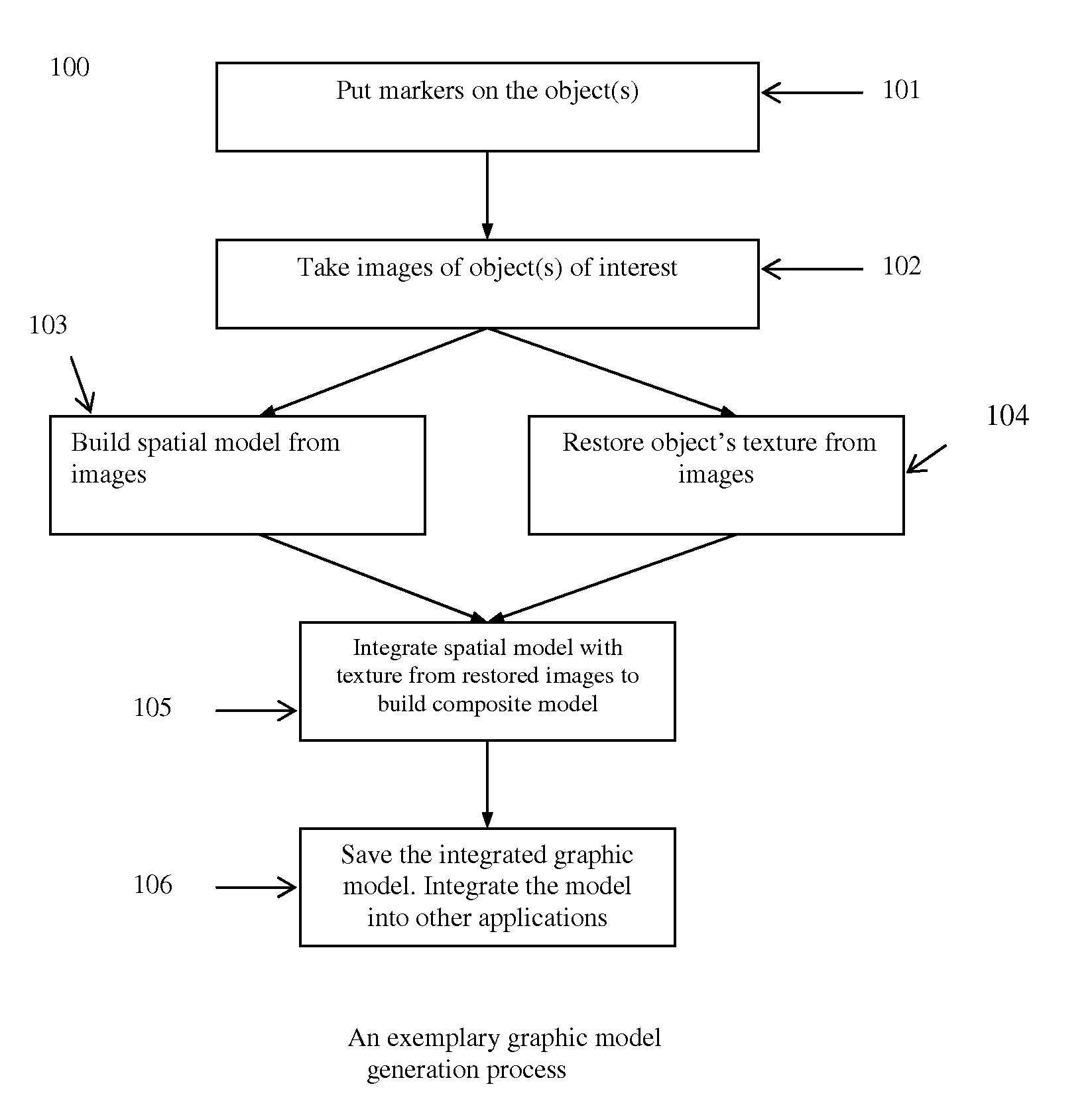
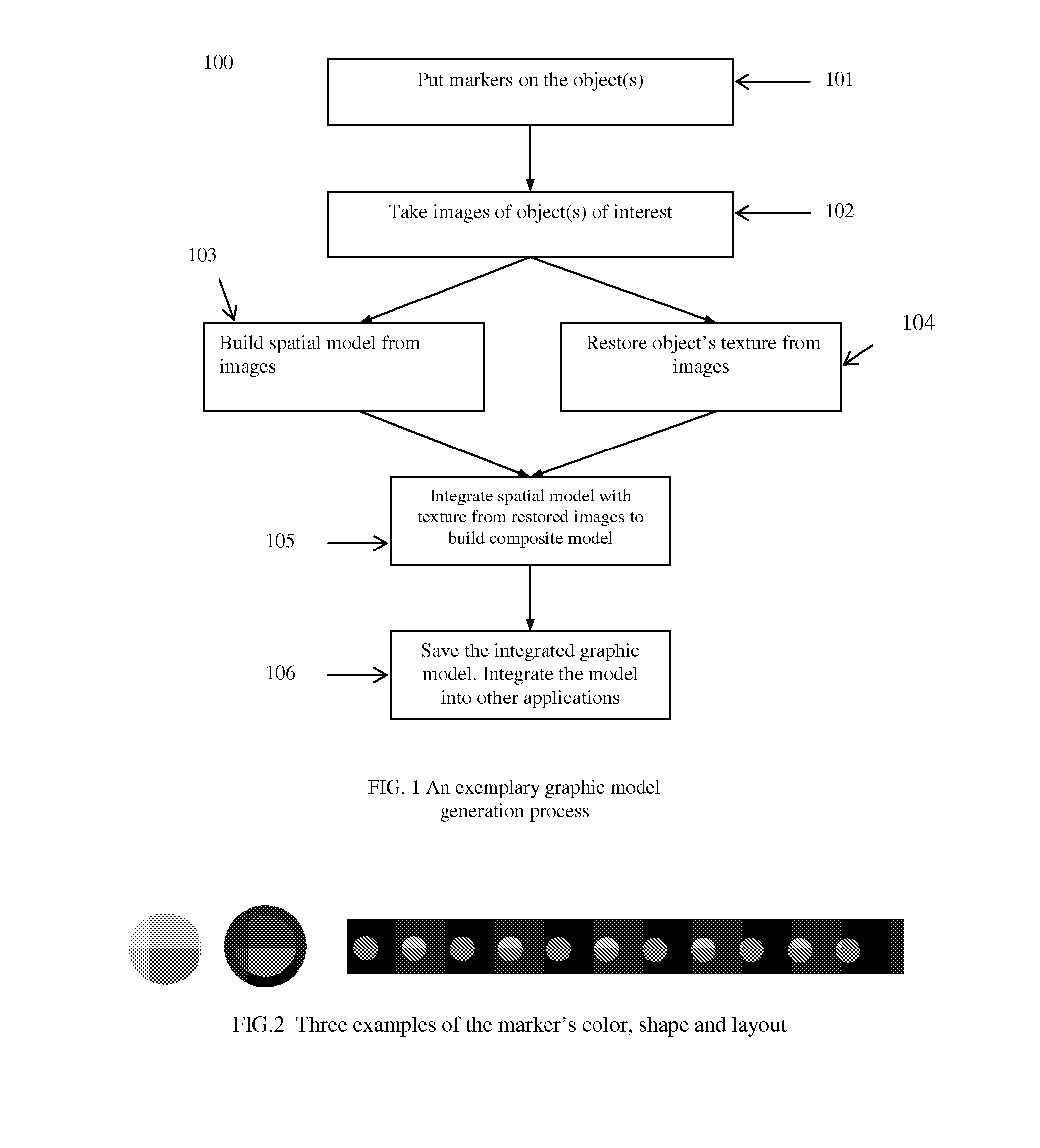
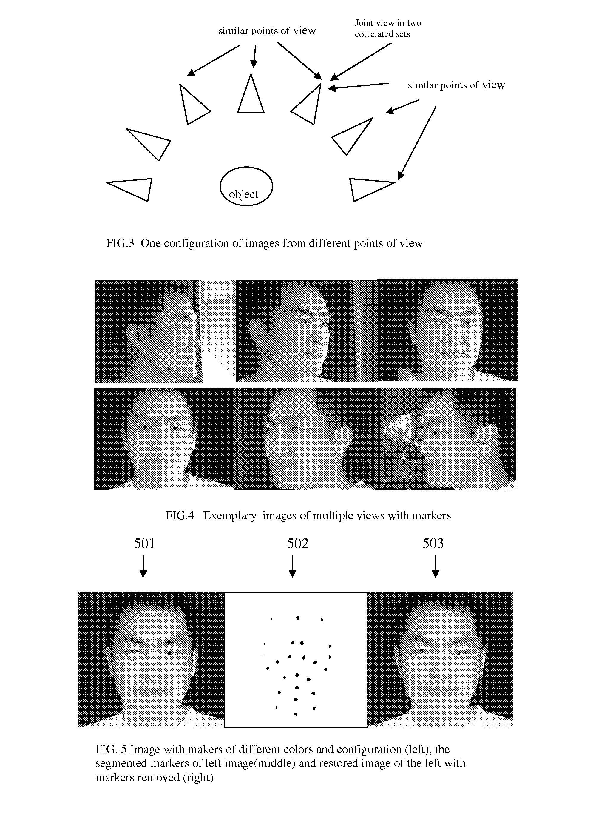
However, conventional procedures to build and / or to deform such graphic model are often complex and may require special imaging devices.
It might be impractical for ordinary people with ordinary cameras to use such procedures.
The availability of these special scanners and the performance requirements of these algorithms may limit such conventional procedures only to a small number of people.
However, two challenges exist.
The first challenge is the recovering of the real color of the object from the raw images because the raw images may not capture the real color of the imaged object due to imaging factors such as lighting.
The other challenge is the stitching of the images of different views into one complete texture image.
However, conventional marker-based methods may require a large number of external markers, and the external markers cover the surface of the object and may corrupt images taken for the object (e.g., change of original color).
The corrupted images used to construct the spatial model can no longer be used to build valid texture maps for the object.
Thus, this disadvantage has limited applications of marker-based methods in the graphic model generation.
Although these marker-less methods may maintain a complete texture, the position information of the feature points may be inaccurate because the feature points are the estimated results of algorithms or the user's judgment.
Because their performance depends upon factors such as the algorithms, user's subjective judgment, the imaging condition and shape of the object, it is hard to achieve accuracy and robustness in the real world with these methods.
Further, the manual labeling process is often very time-consuming, error-prone, and tedious.

Method used


Image

  • Computer graphic generation and display method and system
  • Computer graphic generation and display method and system
  • Computer graphic generation and display method and system

Examples


Embodiment Construction

[0036]Reference will now be made in detail to exemplary embodiments of the invention, which are illustrated in the accompanying drawings. Wherever possible, the same reference numbers will be used throughout the drawings to refer to the same or like parts.

[0037]FIG. 21 shows an exemplary block diagram of computer graphic generation and display system 2100. As shown in FIG. 21, system 2100 may include a processor 2102, a random access memory (RAM) unit 2104, a read-only memory (ROM) unit 2106, a storage unit 2108, a display 2110, an input / output interface unit 2112, a database 2114; a communication interface 2116; and an imaging unit 2120. Other components may be added and certain devices may be removed without departing from the principles of the disclosed embodiments.

[0038]Processor 2102 may include any appropriate type of general purpose microprocessor, digital signal processor or microcontroller, and application specific integrated circuit (ASIC). Processor 2102 may execute seque...


PUM


Abstract

A computer-implemented method is provided for generating and transforming graphics related to an object. The method includes obtaining one or more images taken from different points of view of the object, and a surface of the object is placed with a plurality of external markers such that control points for image processing are marked by the external markers. The method also includes building a spatial model from the one or more images based on the external markers, and processing the images to restore original color of parts of the one or more images covered by the external markers. Further, the method includes integrating texture from the restored images with the spatial model to build an integrated graphic model, and saving the integrated graphic model in a database.

Description

CROSS-REFERENCES TO RELATED APPLICATIONS[0001]This application claims the priority of prior provisional patent application No. 61 / 186,907 filed on Jun. 15, 2009 to Tao Cai.FIELD OF THE INVENTION[0002]The present invention generally relates to computer graphic technologies and, more particularly, to the methods and systems for generating and displaying computer graphics based on graphic models generated from one or multiple images.BACKGROUND[0003]Computer graphics have been used in many areas such as computer-generated animated movies, video games, entertainments, psychology study, and other 2-dimensional (2D) and 3-dimensional (3D) applications. One task involved in generating and displaying computer graphics is to generate and / or to deform a graphic model containing both spatial and color information of an object of interest. There are many implementations of the graphic model, and one commonly-used computer graphic model is a textured surface, which is a combination of a 2D / 3D spa...

Claims


Application Information

Patent Timeline
Patent Type & Authority Applications(United States)
IPC IPC(8): G06T15/20
CPCG06T17/00G06T2200/08G06T2207/30201G06T7/55
Inventor CAI, TAO
Owner CAI TAO
Why Eureka
Try Eureka