Control device for automatic transmission of vehicle

a technology of automatic transmission and control device, which is applied in the direction of digital data processing details, mechanical equipment, instruments, etc., can solve the problems of increased noise or vibration, lack of acceleration feel, and hardly working engine braking, so as to reduce the temperature of the torque converter and ensure the effect of driving

Active Publication Date: 2010-12-16
HONDA MOTOR CO LTD
View PDF16 Cites 15 Cited by
  • Summary
  • Abstract
  • Description
  • Claims
  • Application Information

AI Technical Summary

Benefits of technology

[0013]The present invention is made in view of the above points, and it is an object of the present invention to provide a control device of an automatic transmission for a vehicle capable of suppressing rise in temperature of a torque converter and of ensuring good driveability by generating automatic down shift in a manual shift mode at appropriate timing.
[0020]According to the control device of the automatic transmission for the vehicle of the present invention, by switching the automatic down shift vehicle speed tables in the manual shift mode in accordance with the driving force margin of the vehicle, it is possible to generate the automatic down shift at appropriate timing in response to lowering of the driving force margin of the vehicle even in a situation in which the driving force margin of the vehicle is determined by means of influence on other factors in addition to the estimated uphill gradient. Therefore, it is possible to effectively prevent the vehicle speed from stagnating. This makes it possible to prevent the slip ratio of the lock-up clutch from stagnating in the loose region for a long time. Therefore, it is possible to effectively suppress rise in temperature of the hydraulic oil due to heat generation of the torque converter.
[0021]Further, since the automatic down shift vehicle speed tables are switched in accordance with the driving force margin of the vehicle, it becomes possible to suppress generation of unnecessary automatic down shift when the driving force margin of the vehicle is sufficient.
[0024]According to the control device of the automatic transmission for the vehicle of the present invention, it is possible to suppress rise in temperature of a torque converter and secure driveability by generating automatic down shift in a manual shift mode at appropriate time in accordance with a driving force margin of a vehicle.

Problems solved by technology

Namely, in setting of a gear (gear ratio) required by a driver, acceleration feel is lacking due to lowering of the number of revolutions of an engine, or engine braking hardly works by selecting a high gear ratio at low vehicle speed.
However, since variation in engine torque is directly transmitted to a drive system in the engagement region of the lock-up clutch, broadening of the engagement region causes increase in noise or vibration.
However, when the lock-up clutch is caused to continuously slip, a calorific value of a friction member (facing member) with which the lock-up clutch is provided increases to become high temperature.
In the case where such a state of high temperature continues for a long time, a mirrored process, abrasion, carbonization or the like of a surface of the friction member occurs, there is a fear that a decrease of frictional force occurs.
Further, when the friction member becomes high temperature, an increase in a slippage amount of the torque converter causes heat generation by a work loss to increase in addition to heat generation of the friction member.
Thus, there has been a problem that automatic down shift is not always generated at appropriate timing in the case where switching of vehicle speed tables is carried out on the basis of only the driving gradient.
For example, in the case of a cruise driving state on an uphill road (traction state on the uphill road and the like), the driving force margin of the vehicle becomes smaller, vehicle speed does not increase smoothly and tends to stagnate.
However, automatic down shift may not be generated even in such a situation.
In this way, there has been a fear that vehicle speed stagnates in a region in which a slip ratio of the lock-up clutch is large (loose region) for a long time if a state in which the driving force margin is small continues and the vehicle speed does not increase smoothly.
There has been a problem that this causes a facing calorific value of the lock-up clutch to increase and temperature of hydraulic oil (ATF) in the torque converter is thereby raised.
Further, there has been a problem that automatic down shift is generated even in a situation that down shift is not required essentially, for example, the case where the driving force margin is a medium degree or more and the vehicle speed increases smoothly when a vehicle speed table for an uphill road is selected in automatic down shift control.
Therefore, a problem that the slip ratio of the lock-up clutch stagnates in the loose region for a long time hardly occurs.
There has been a problem that this causes driving force during deceleration (engine brake) of the vehicle to overwork to deteriorate driveability of the vehicle.

Method used


Image

  • Control device for automatic transmission of vehicle
  • Control device for automatic transmission of vehicle
  • Control device for automatic transmission of vehicle

Examples


Embodiment Construction

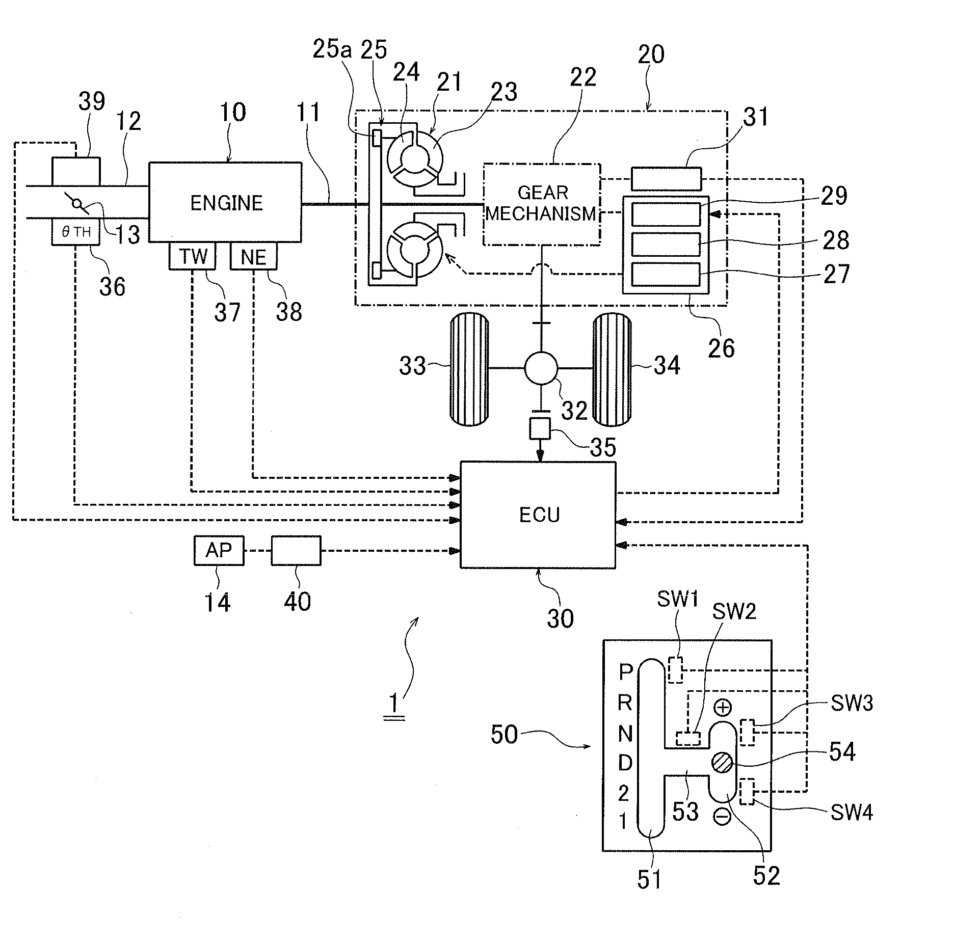
[0033]Hereinafter, an embodiment of the present invention will be described in detail with reference to the appending drawings. FIG. 1 is a schematic view showing a drive system mounted on a vehicle and a configuration of a control device thereof. The drive system shown in FIG. 1 includes an automatic transmission 20 connected to a crank shaft 11 of an engine 10. The automatic transmission 20 includes a torque converter 21 connected to the crank shaft 11 and a multi-stage shift gear mechanism 22 connected to an output side of the torque converter 21. The torque converter 21 has a pump impeller 23 and a turbine runner 24. The torque converter 21 is also provided with a lock-up clutch 25 for connecting the pump impeller 23 to the turbine runner 24. The torque converter 21 and the multi-stage shift gear mechanism 22 are controlled by a hydraulic control mechanism 26.

[0034]The hydraulic control mechanism 26 includes an on / off type solenoid valve (hereinafter, referred to as “first solen...


PUM


Abstract

A driving force margin of a vehicle is calculated on the basis of an engine load, vehicle speed, travel resistance and estimated uphill gradient. A gear is determined on the basis of predetermined gear shifting characteristics at least from the vehicle speed and the engine load in an automatic shift mode. Automatic down shift is generated in the case where the vehicle speed becomes lower than vehicle speed on an automatic down shift vehicle speed table set up in accordance with the gear when the operation is switched from the automatic shift mode to a manual shift mode. The automatic down shift vehicle speed table is corrected so as to shift an automatic down shift line to a high vehicle speed side or low vehicle speed side in accordance with the magnitude of the calculated driving force margin of the vehicle.

Description

CROSS-REFERENCE TO RELATED APPLICATION[0001]The present disclosure relates to subject matter contained in Japanese Patent Application No. 2009-140174, filed on Jun. 11, 2009, the disclosure of which is expressly incorporated herein by reference in its entirety.BACKGROUND OF THE INVENTION[0002]1. Field of the Invention[0003]The present invention relates to a control device for an automatic transmission of a vehicle, and particularly, the present invention relates to a control device for an automatic transmission of a vehicle capable of generating automatic down shift in a manual shift mode at appropriate timing.[0004]2. Description of the Related Art[0005]An automatic transmission for a vehicle is provided with a plurality of ranges (shift positions such as Parking (P), Reverse (R), Neutral (N), Drive (D), Second (2) and Low (1)). The Drive range that is an automatic gear shifting range functions as an automatic shift mode in which automatic gear shifting is carried out on the basis ...

Claims


Application Information

Patent Timeline
Patent Type & Authority Applications(United States)
IPC IPC(8): G06F19/00F16H59/18F16H59/24F16H59/44F16H59/66F16H59/68F16H61/02F16H61/10F16H61/68
CPCF16H59/66F16H61/0213F16H2061/0225F16H2061/0232F16H2059/663
Inventor MURATA, RYUJITAKEO, HIROYUKISASAHARA, KAZUMA
Owner HONDA MOTOR CO LTD
Why Eureka
Try Eureka