Modulated Power Burner System And Method

a power burner and module technology, applied in the field of gas burners, can solve the problems of inability to provide efficient combustion across the entire operating range of the appliance, inability to provide consistent combustion efficiency, and system configuration to provide efficient operation, so as to avoid excessive delay in achieving the desired lower heat output

Active Publication Date: 2010-12-23
WAYNESCOTT FETZER
View PDF104 Cites 21 Cited by
  • Summary
  • Abstract
  • Description
  • Claims
  • Application Information

AI Technical Summary

Benefits of technology

[0009]In another embodiment, the control modulates the combustion air blower to a reduced speed and modulates the gas valve to track a gradually reducing speed of the combustion air blower when a demand for lower heat output is received by the system. When the gas valve is within a predetermined range of a final, desired gas valve position that corresponds to the lower heat

Problems solved by technology

While such induced draft systems may be able to achieve higher ratios of air in the combustion chamber, these systems still rely upon available air from the environment and therefore may provide inconsistent efficiencies of combustion.
While various types of controllable burner systems are available, many convention

Method used


Image

  • Modulated Power Burner System And Method
  • Modulated Power Burner System And Method
  • Modulated Power Burner System And Method

Examples


Embodiment Construction

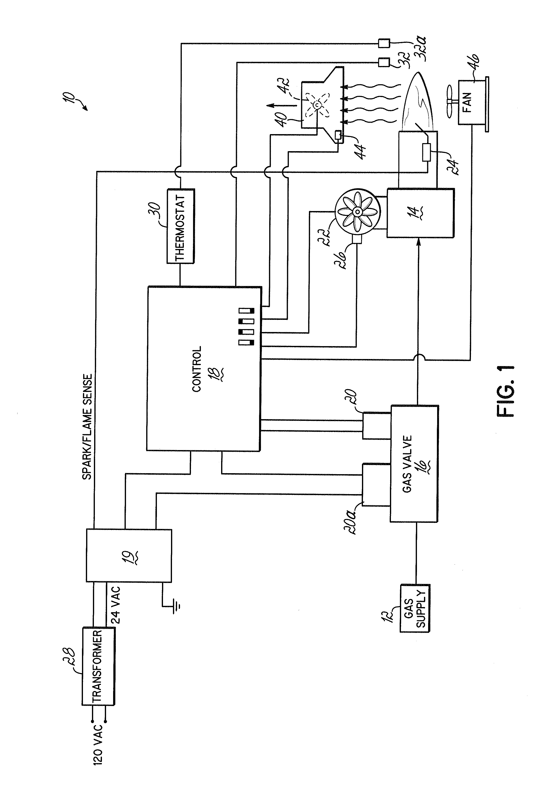
[0020]FIG. 1 is a schematic illustration depicting an exemplary embodiment of a powered gas burner system 10. Pressurized gas from a supply 12 is directed to a burner 14 through a modulating gas valve 16 that is in communication with a control 18. The control 18 sends signals to the gas valve 16 to cause the valve to move to a desired position and thereby provide a desired gas flow rate to the burner 14. For example, in the embodiment shown, the gas valve 16 includes a solenoid 20 that receives a voltage or other signal from the control 18 to cause the gas valve 16 to move to a desired valve position. The gas valve 16 may further include a second solenoid 20a configured to place the valve in either an open condition or a closed condition. The second solenoid 20a communicates with an ignition control 19 that is in communication with an ignition device 24. Ignition control 19 sends a signal to the second solenoid 20a to place the valve in an open condition only when a flame is detecte...


PUM


Abstract

A power burner system for use with a heating appliance includes a burner tube, a gas valve for providing gas to the burner tube, and a variable speed combustion air blower for mixing air with the gas provided to the burner tube. The burner system further includes a control in communication with the gas valve and the combustion air blower. The control may also be in communication with various other devices of an appliance, such as a variable speed air-circulating fan, a variable speed exhaust fan, or various sensors associated with the heating appliance. The control modulates the gas valve and the combustion air blower to maintain substantially stoichiometric conditions of the gas and air provided to the burner tube and as a function of signals from at least one of the devices. In one embodiment, the burner system may be used in a conveyor oven.

Description

CROSS REFERENCE TO RELATED APPLICATIONS[0001]This application is a divisional of U.S. patent application Ser. No. 11 / 738,111, filed Apr. 20, 2007 (pending), which claims the priority of U.S. Provisional Patent Application Ser. No. 60 / 862,131, filed Oct. 19, 2006 (expired), the disclosures of which are hereby incorporated by reference herein in their entirety.TECHNICAL FIELD[0002]The present invention relates generally to gas burners for heating, and more particularly to a powered burner for use in heating appliances.BACKGROUND OF THE INVENTION[0003]Powered gas burners are heating devices that utilize a fan or blower to mix combustion air with gas from a supply and to direct the air / gas mixture to a burner tube at a pressure that is higher than atmospheric pressure. Powered burners are therefore distinguishable from atmospheric burners which rely solely on the static pressure of gas from a supply to provide an air / gas mixture at burner outlets where the air / gas mixture may be ignited...

Claims


Application Information

Patent Timeline
IPC IPC(8): A21B1/42F23N1/02F23N5/00
CPCF23N1/045F23N2033/10F23N2033/08F23N2233/08F23N2233/10
Inventor COX, DONALD W.NOMAN, SYED MOHAMMAD SHIBLEE
Owner WAYNESCOTT FETZER
Why Eureka
Try Eureka