
Electron gun used in particle beam device

a particle beam and electron gun technology, applied in the direction of cathode ray tubes/electron beam tubes, instruments, electric discharge tubes, etc., can solve the problems of thermal field-emission sources having a further disadvantage, time, effort and cost for providing such good conditions, etc., to increase the strength of electric field, easy to achieve, and the brightness of the electron gun according to the system

Active Publication Date: 2010-12-23
NORDSON CORP
View PDF7 Cites 10 Cited by
  • Summary
  • Abstract
  • Description
  • Claims
  • Application Information

AI Technical Summary

Benefits of technology

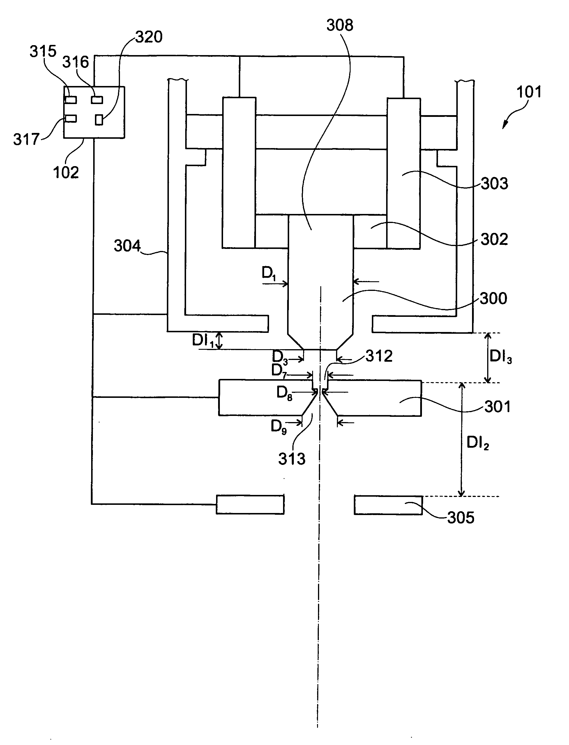
[0015]The system described herein allows the use of a thermionic source as the electron source. Since a thermionic source may normally have a larger size than a field-emission source, the vacuum conditions required for operating the electron gun may not be as high as UHV conditions. The electron gun according to the system described herein may be operated with a residual pressure of about 10−5 mbar (for example, for a tungsten filament as the electron source) to 10−7 mbar (for example, for a rare earth hexaboride as the electron source). These vacuum conditions are relatively easy to achieve. Moreover, the voltage between the electron source and the first electrode can be adjusted to relatively low values. These low values and the relatively large size of the electron source yield an electric field strength at the electron source (for example 107 V / m) which is well below the electric field strength required for field emission (for example >5×10⁸ V / m).
[0016]Furthermore, the brightness β of the electron gun according to the system described herein may be relatively high. The first electrode, which may be configured to control a path of electrons emitted from the electron emission surface, increases the strength of the electric field near the electron emission surface. This results in a decrease of a negative space charge in the area of the electron emission surface. This, in turn, results in a higher acceleration of electrons emitted from the electron emission surface towards the third electrode. This again results in a lower energy spread of the electrons emitted from the electron emission surface and lowers the chromatic aberration δrC. Stochastic Coulomb interactions between electrons (known as Boersch effects) increase the chromatic aberration δrC, especially at a crossover where the electrons are rather close to each other. Since the first voltage, the second voltage and the third voltage can be adjusted to receive no crossover of electrons, the chromatic aberration δrC is reduced. Moreover, the effective radius reff of the electron source can be reduced due to the low chromatic aberration δrC. Since these values are comprised in the denominator of Equation 3, the brightness β of the electron gun according to the system described herein is relatively high.
[0017]According to the prior art, an emission current in the range of a few μA (for example 1 μA to 5 μA) which is transferred via the first electrode was achieved. Therefore, a power supply unit capable of providing such an emission current was used. The system described herein, however, also facilitates a high emission current in the range of a few mA (for example 1 mA to 5 mA) which is transferred via the first electrode. Therefore, at least one power supply unit capable of providing such an emission current in the range of a few mA may be used for the system described herein.
[0031]A method for controlling an electron gun as mentioned above may comprise the following steps: applying the first voltage to the first electrode; applying the second voltage to the second electrode; and applying the third voltage to the third electrode, and in which applying the first voltage, the second voltage and the third voltage is carried out such that a crossover of electrons emitted from the electron source is avoided.

Problems solved by technology

This is a disadvantage because the time, effort and costs for providing such good conditions are relatively high.
Thermal field-emission sources have a further disadvantage due to their relatively larger energy spread with respect to the electrons emitted from the electron source.

Method used


Image

  • Electron gun used in particle beam device
  • Electron gun used in particle beam device
  • Electron gun used in particle beam device

Examples


Embodiment Construction

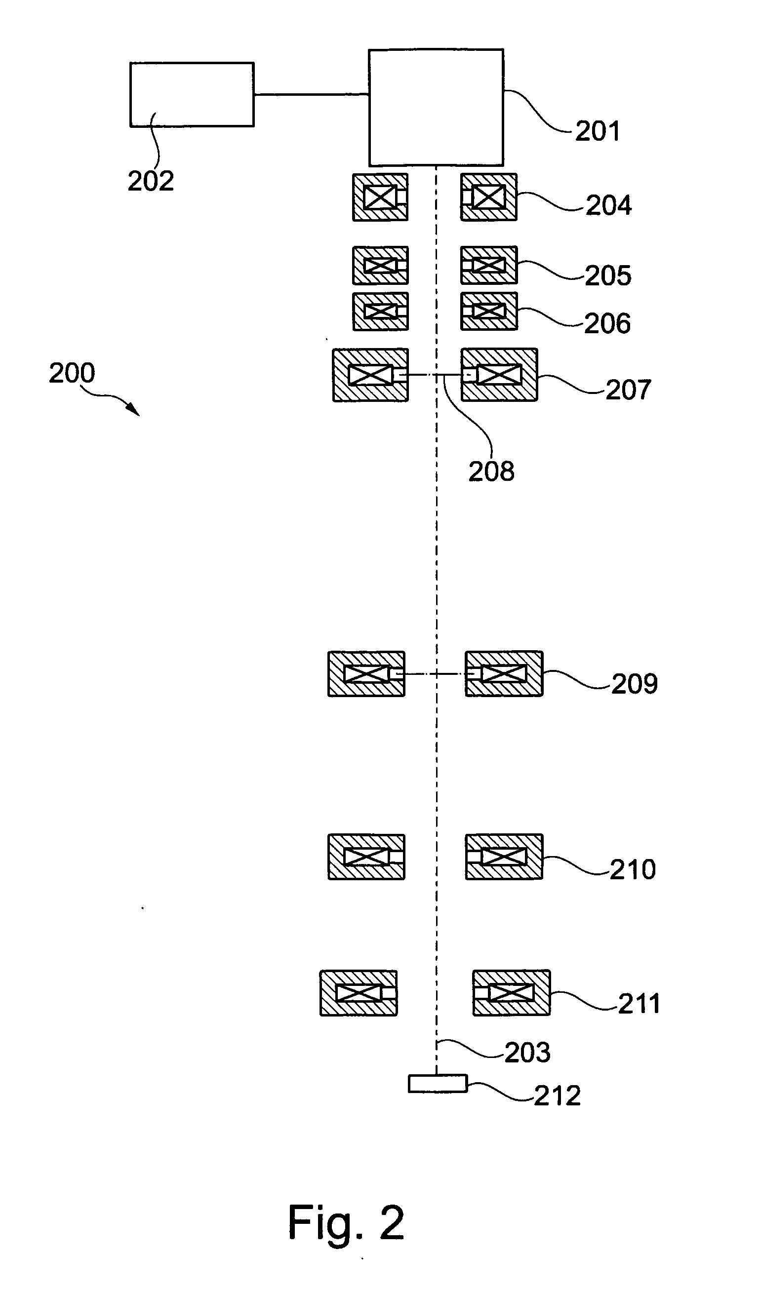
[0044]The system described herein will now be further explained with respect to particle beam devices, in particular to two electron beam devices. It should be noted that the system described herein is not limited to these electron beam devices, and instead may be arranged and / or used in any suitable particle beam device.

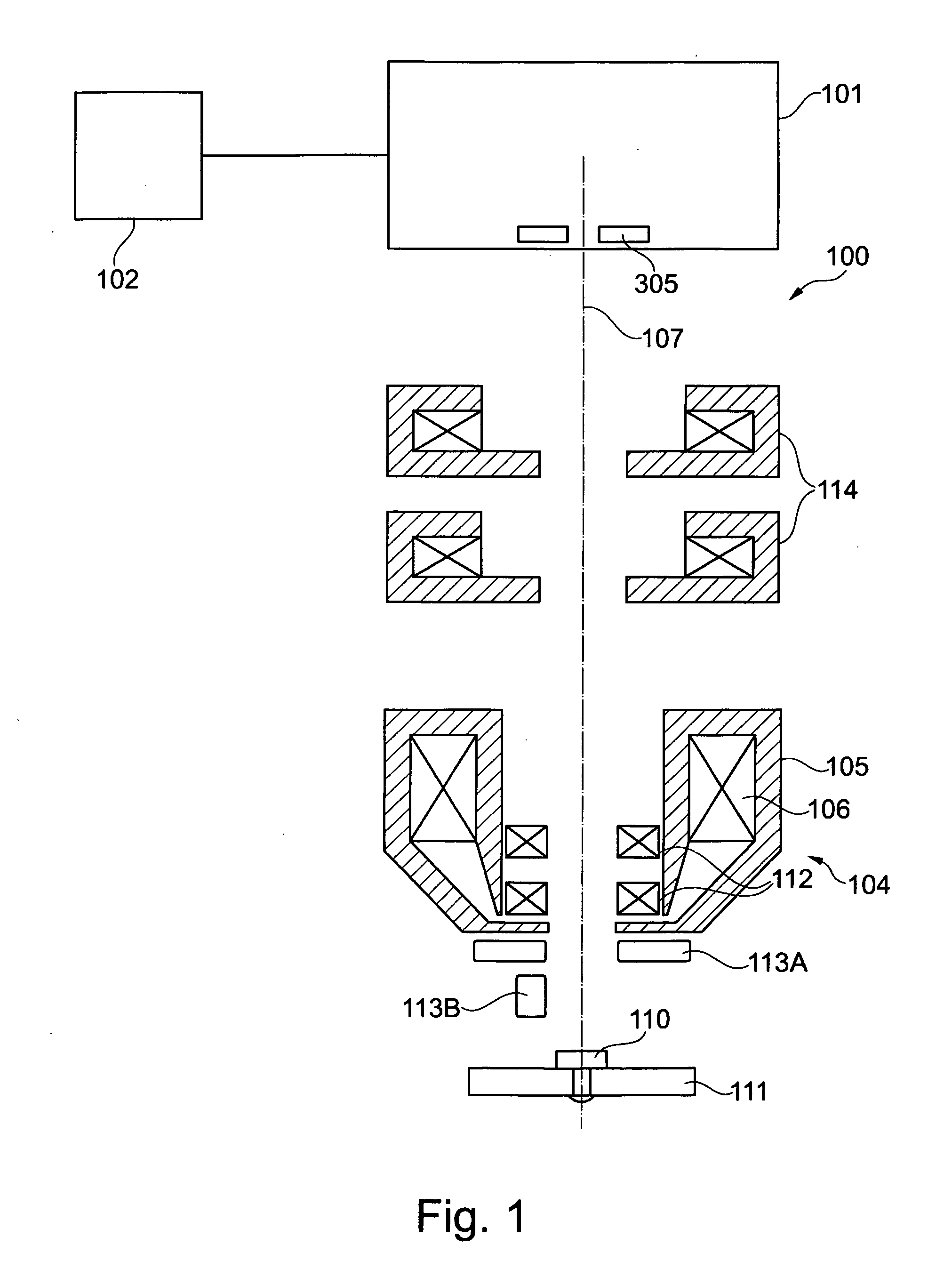
[0045]FIG. 1 shows a schematic drawing of a scanning electron microscope 100 (hereinafter referred to as SEM) according to an embodiment of the system described herein. The SEM 100 may comprise an electron gun 101 providing electrons. The electron gun 101 may be connected to a supply unit 102 which supplies high voltages to the electron gun 101. The electron gun 101 and the supply unit 102 will be described in detail below.

[0046]The SEM 100 may also comprise a condenser 114 and an objective lens 104 in the direction of the optical axis 107 of the SEM 100, starting from the electron gun 101. The objective lens 104 may comprise pole shoes 105 having coils 106. A sampl...


PUM


Abstract

An electron gun used in a particle beam device, for example in an electron microscope, has a relatively good brightness and may be operated under vacuum conditions which can be easily achieved (i.e., for example, at a residual pressure of about 10−6 or 10−7 mbar). The electron gun comprises an electron source having an electron emission surface. Furthermore, the electron gun comprises a first electrode configured to control a path of electrons emitted from the electron emission surface, a second electrode which is configured to suppress emissions of electrons from a side surface of the electron source and a third electrode configured to accelerate electrons emitted from the electron source to a final energy. A first voltage, a second voltage and a third voltage are adjusted to avoid any crossover of electrons emitted from the electron emission surface.

Description

TECHNICAL FIELD[0001]This application relates to an electron gun used in a particle beam device, for example in an electron microscope such as a scanning electron microscope (SEM) and / or a transmission electron microscope (TEM). Moreover, this application relates to an electron beam device comprising an electron gun as well as to a method for controlling an electron gun.BACKGROUND OF THE INVENTION[0002]It is known to use two kinds of electron sources in an electron beam device: the first kind is a thermionic source which emits electrons when heated. The second kind is a field-emission source which emits electrons when an intense electric field is applied to it.[0003]A thermionic source uses, for example, a tungsten filament, a pointed emitter of a single crystal or a sintered compound of lanthanum hexaboride (LaB6) or cerium hexaboride (CeB6). If those materials are heated to a sufficiently high temperature, the electrons of the materials receive sufficient energy to overcome the na...

Claims


Application Information

Patent Timeline
IPC IPC(8): H01J29/51H01J29/48
CPCH01J37/063H01J2237/06375H01J2237/06341H01J2237/06308
Inventor HAYN, ARMIN HEINZ
Owner NORDSON CORP
Learn More