Raw material for shot-peening materials, finished wire, method of manufacturing shot-peening materials, and shot-peening materials

Inactive Publication Date: 2010-12-23
SINTOKOGIO LTD
View PDF0 Cites 1 Cited by
  • Summary
  • Abstract
  • Description
  • Claims
  • Application Information

AI Technical Summary

Benefits of technology

[0009]The method of manufacturing the shot-peening materials of the present inventions is characterized in that it comprises the steps of cutting and plastic-forming the finished wire of the second feature to make raw shot-peening materials, and quenching and tempering them. The present inventions provide shot-peening materials that are efficiently manufactured and have a good quality, since they are made from the finished wire, which has a proper elongation and has a reliable quality.
[0010]The tempering parameters are defined by the following equation: T{(21.3 −5.8×[C])+log(t)}: where T denotes the tempering temperature (K), t the tempering time (hr), and [C] the carbon content (%). The tempering temperature T and the carbon content C are selected so that the parameters become 6200-7300. When the tempering temperature T, the carbon content C, and the tempering time t, are selected so that the parameters become 6200-7300, the coarsening of crystalline grains is prevented and the residual stress is relieved, to increase toughness. Thus, that selection is preferable. The method may further comprise the step of plastic-forming the raw shot-peening materials. This method has an advantage in that almost no breaking is generated during a shot-peening process, because the corners of the shot-peening materials are rounded off. Plastic-forming the raw shot-peening material means to make the raw shot-peening material in a spherical shape from a short piece that is made by cutting the finished wire by plastic-forming. That is, the raw shot-peening materials are not rounded by cutting or grinding.
[0011]The method of manufacturing the shot-peening materials of the present inventions is further characterized in that it comprises the steps of wiredrawing a raw material for the shot-peening materials of the first feature to obtain a wire, repeatedly annealing and cold-drawing the wire to obtain a finished wire, obtaining the raw shot-peening materials by cutting the finished wire and plastic-forming, and quenching and tempering the raw shot-peening materials. It has an advantage in that the crystalline grains are refined and the toughness is recovered after the heat treatment.
[0012]The method of manufacturing the shot-peening materials of the present inventions is further characterized in that the quenching temperature is 820-850° C. in the aforementioned method. It has an advantage in that almost no residual austenite is generated, and overall, martensite is uniformly obtained in the structure.
[0013]The shot-peening materials of the present inventions are those manufactured by the methods that are described above

Problems solved by technology

However, when a bearing steel that is not modified from a standard steel (e.g., a high carbon chromium bearing steel, SUJ2 of JIS (Japan Industrial Standards) G4805, of which the components are shown in Table 2) has been used as a raw material for shot-peening materials, there has been a problem of the wire breaking.
This does not improve the productivity of the shot-peening materials.
Thus, the productivity i

Method used


Image

  • Raw material for shot-peening materials, finished wire, method of manufacturing shot-peening materials, and shot-peening materials
  • Raw material for shot-peening materials, finished wire, method of manufacturing shot-peening materials, and shot-peening materials
  • Raw material for shot-peening materials, finished wire, method of manufacturing shot-peening materials, and shot-peening materials

Examples


example 1

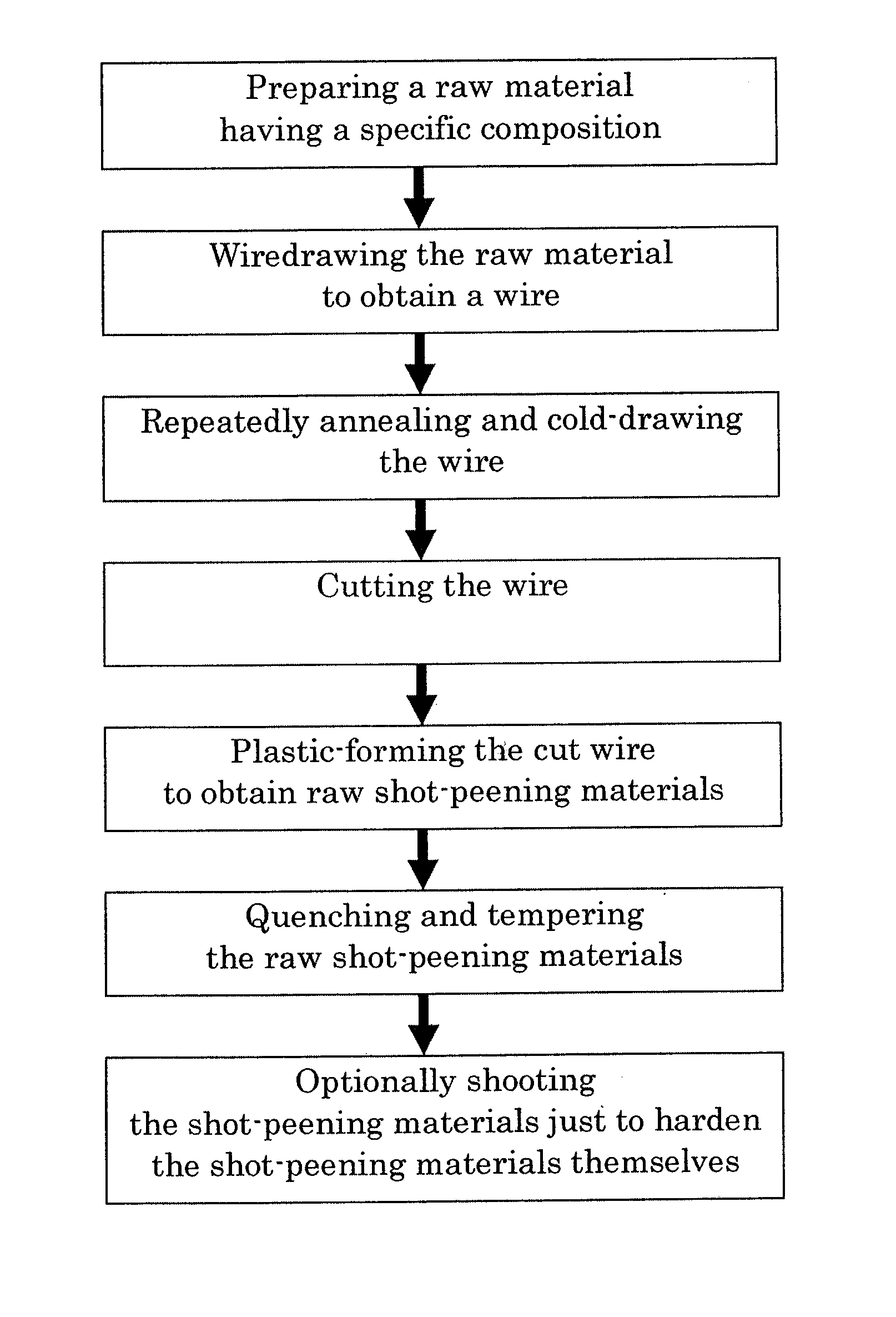
[0031]The flowchart of manufacturing shot-peening materials by using the raw material for the shot-peening materials of the present inventions is shown in FIG. 1. By reference to FIG. 1, manufacturing shot-peening materials is described below. As in the flowchart, at a first step a raw material having the components of Table 1 is prepared. At a second step the raw material is wiredrawn to be a wire. At a third step the wire is repeatedly annealed and cold-drawn. At a fourth step the wire is cut. At a fifth step the cut wire is subject to plastic formation. At a sixth step it is quenched and tempered. At a seventh step it is shot just to harden the shot-peening materials themselves.

[0032]Comparisons between example 1 and the bearing steel of Table 2, SUJ of JIS G4805, during the first three steps, are shown in Table 3. The wire after the wiredrawing of the second step has a diameter of 1.6 mm and a hardness of 320 HV.

TABLE 3Working ExampleComparative ExampleContaining 0.95-1.10% carb...

example 2

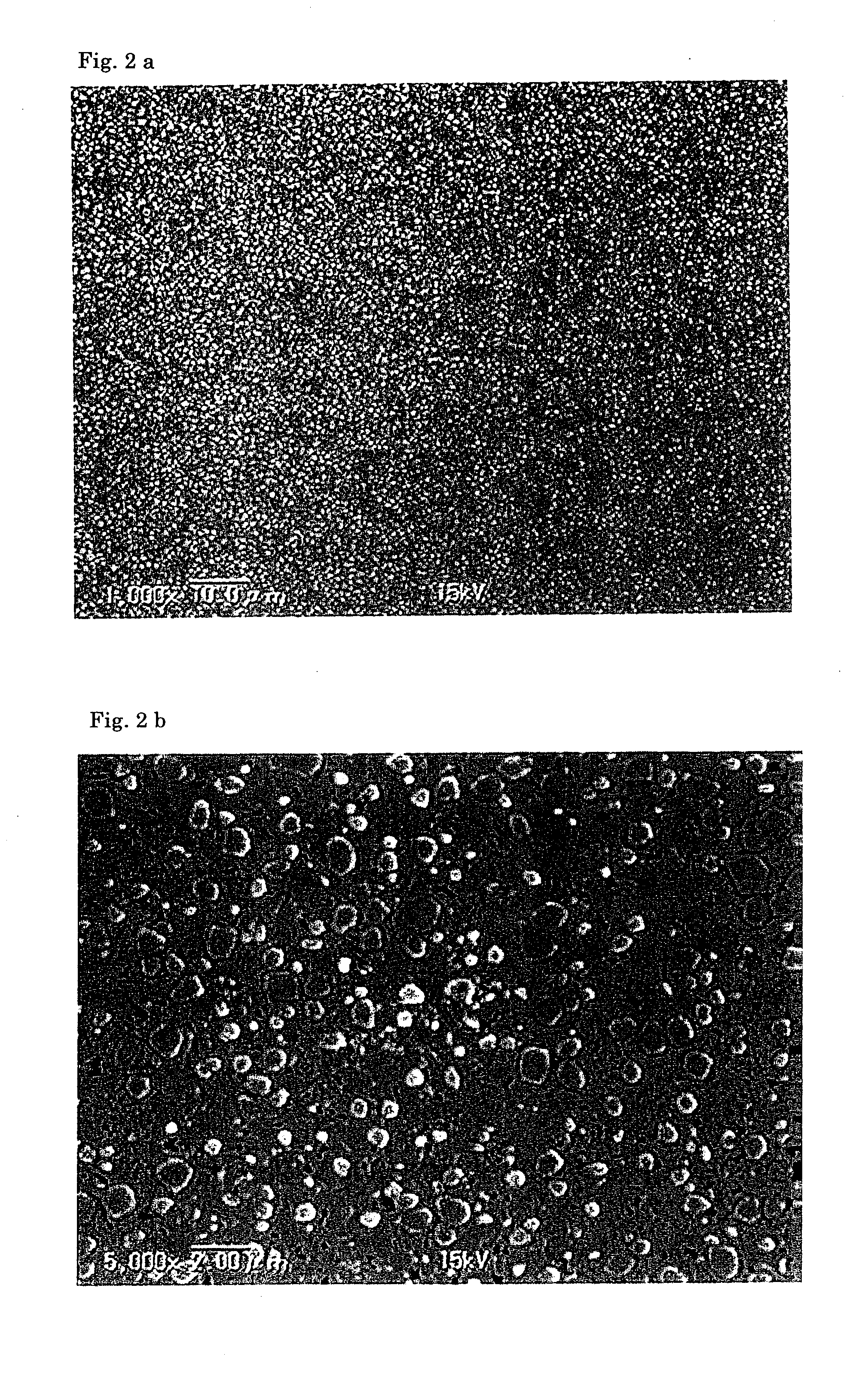
[0043]The conditions and results of shot-peening in which the shot-peening materials of the present inventions are shot against a work are shown in Table 10. Example 2 shows that the shot-peening materials of the present inventions, of which the hardness is 950 HV, cause a smaller amount to be scraped off when they are shot against a hard work. They also cause work-hardening and larger residual stress in the work (see Experiment Nos. 11-17). The hardness of the materials is initially 950 HV, but possibly increases to 1050 HV after shot-peening.

[0044]The amount being scraped off is measured as follows:

A Method of Measuring an Amount Being Scraped Off

[0045]The diameter of a work before shot-peening and that after shot-peening are measured by a laser dimension-measuring device. The amount is calculated by the following equation. It is the mean value of ten measurements (n=10). The measurement is performed at the center of the target of the shot (where the maximum amount being scraped o...


PUM

PropertyMeasurementUnit
Temperatureaaaaaaaaaa
Fractionaaaaaaaaaa

Abstract

The purposes of the present inventions are to provide a raw material for shot-peening materials wherein breaking a wire is prevented in obtaining a finished wire to improve the productivity, to provide a finished wire and a method of manufacturing shot-peening materials by which productivity is improved, and to provide shot-peening materials that are manufactured by that method. The finished wire, of which the area of carbides with a particle size of 2 μm or less is 80% or more of the total area, is manufactured by the steps of wiredrawing a raw material to obtain a wire, and repeatedly annealing and cold-drawing the wire. The raw material for the shot-peening materials comprises, by mass %, 0.95-1.10% carbon, 0.15-0.30% silicon, 0.40% or less manganese, 0.020% or less phosphorus, 0.010% or less sulfur, 1.40-1.60% chromium, 0.0015% or less oxygen, and the remaining materials of iron and unavoidable impurities. The method of manufacturing the shot-peening materials uses that raw material. The shot-peening materials are manufactured by that method.

Description

TECHNICAL FIELD[0001]The present inventions relate to a raw material for shot-peening materials, a finished wire, a method of manufacturing shot-peening materials, and shot-peening materials.BACKGROUND ART[0002]In an existing process of manufacturing shot-peening materials, a raw material, e.g., so-called bearing steel, is wiredrawn to obtain a wire. The wire is cut at the same length as its diameter. The cut wire is then thrown at a rigid wall to round off its edges. The rounded-off wire is ground to a predetermined degree of sphericity. Then, it is quenched and tempered to get a predetermined Vickers hardness. This process is well known (e.g., Japanese Laid-open Publication No. 2001-79766).DISCLOSURE OF INVENTION[0003]However, when a bearing steel that is not modified from a standard steel (e.g., a high carbon chromium bearing steel, SUJ2 of JIS (Japan Industrial Standards) G4805, of which the components are shown in Table 2) has been used as a raw material for shot-peening materi...

Claims


Application Information

Patent Timeline
IPC IPC(8): C22C38/18C21D9/52
CPCB24C11/00
Inventor KOBAYASHI, YUJITSUJI, TOSHIYA
Owner SINTOKOGIO LTD
Why Eureka
Try Eureka