Foamed Fluoropolymer Article

a fluoropolymer and article technology, applied in the direction of plastic/resin/waxes insulators, liquid handling, stoppers, etc., can solve the problems of loss of productivity, reduced line speed, and inability to disclose compositions that provide the desired insulation, so as to reduce the dielectric of foamed wire insulation and accelerate signal transmission

a fluoropolymer and article technology, applied in the direction of plastic/resin/waxes insulators, liquid handling, stoppers, etc., can solve the problems of loss of productivity, reduced line speed, and inability to disclose compositions that provide the desired insulation, so as to reduce the dielectric of foamed wire insulation and accelerate signal transmission

US20100326697A1Inactive Publication Date: 2010-12-30EI DU PONT DE NEMOURS & CO

Image

  • Foamed Fluoropolymer Article
  • Foamed Fluoropolymer Article
  • Foamed Fluoropolymer Article

Examples


example 1

Sample Preparation and Process Description

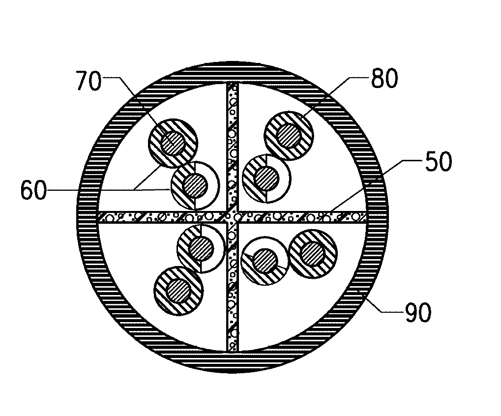
[0048]A triple foam nucleant package of the present invention comprised of boron nitride (91.1±0.5 wt %), calcium tetraborate (2.5±0.2 wt %) and Zonyl® BAS (6.4±0.2 wt %) was used. This nucleant package was compounded into FEP TE9494 fluoropolymer (manufactured by E.I. DuPont de Nemours & Co., Wilmington, Del.), a TFE / HFP / PEVE perfluoropolymer with a melt flow rate (MFR) ˜30 g / 10 min to form a master batch having a boron nitride content of approximately 4 wt % of the resultant composition. Pellets were formed via compounding operations performed on a Kombi-plast extruder consisting of a 28 mm twin-screw extruder and a 38 mm single screw extruder. The master batch pellets and pellets of the base fluoropolymer (FEP TE9494) were dry blended at a ratio of 1:9 to form a foamed thermoplastic composition which was subsequently fed to a Nokia-Maillefer 45 mm extrusion wire-line to extrude insulation onto AWG 23 solid copper conductor (22.6 mil=0.57 ...


PUM

PropertyMeasurementUnit
diameteraaaaaaaaaa
melt flow rateaaaaaaaaaa
diameteraaaaaaaaaa

Abstract

The present invention discloses an article made from a foamable thermoplastic polymer composition. The foamable composition of the article includes a partially-crystalline melt processible perfluoropolymer and a foam nucleating package. The foamable composition of the article has a uniform foam cell size where the foam cell size of at least 90% of the foamed cells is 50 micrometers or less. The foam nucleating package ranges from 0.1 to 10 wt % of the combined weight of the perfluoropolymer and the foam nucleating package.

Description

FIELD OF THE INVENTION[0001]The present invention relates to an article made using foamed thermoplastic polymer. More particularly, the present invention relates to an article made from a foamed thermoplastic polymer composition that combines a foam nucleating package with a high melt flow fluoropolymer.BACKGROUND OF THE INVENTION[0002]There are a variety of problems faced by manufacturers who use fluoropolymers for foamed articles, (e.g. insulated conductor manufacturers), that are not resolved by currently available conductor insulation materials. One such problem for these manufacturers is that the extrusion / melt draw-down process is carried out under a variety of conditions and parameters, resulting in variation of the physical and electrical characteristics of the foamed fluoropolymer for the manufacturers. The manufacturers seek to minimize the variation of the foamed fluoropolymer characteristics.[0003]Another concern of the manufacturers is the economics of extruding the flu...

Claims


Application Information

Patent Timeline
30 Dec 2010
Publication
US20100326697A1
IPC
H01B3/30; C08L27/12; B32B1/08
CPC
C08J9/0033; C08J9/0038; C08J9/0066; Y10T428/1376; C08J2327/12; H01B3/445; C08J2203/06
Inventors
VENKATARAMAN, SUNDAR KILNAGAR; YOUNG, ROBERT THOMAS