Resistor device

a resistor device and resinsealed technology, applied in the direction of sustainable manufacturing/processing, semiconductor/solid-state device details, final product manufacturing, etc., can solve the problems of poor heat dissipation efficiency and complicated manufacturing process, and achieve the effect of reducing the temperature of the resistance body and the resistor device, increasing the power capacity of the resistor device, and efficient absorbing

Active Publication Date: 2010-12-30
KOA CORP
View PDF6 Cites 23 Cited by
  • Summary
  • Abstract
  • Description
  • Claims
  • Application Information

AI Technical Summary

Benefits of technology

[0009]According to the present invention, the heat generated at the resistive plate of metal plate material, especially at its upper side, can be efficiently absorbed by the radiative plate of metal plate material spaced from the resistive plate and intercrossed on the resistive plate. Further, the heat can conduct through the terminal portions of the radiative plate, which is disposed to be bent along end face and bottom face of the molded resin body, to a cooling body, which is provided on a mounting board. Further, by fixing portion of the radiative plate, which is disposed on central portion of the resistor device at bottom face of the molded resin body, to a cooling pad on mounting board by soldering, the central portion

Problems solved by technology

However, since the heat dissipating electrode is disposed at bottom face of the ceramics substrate, heat dissipating route is limited to one direction from heat generating resistance body to h

Method used


Image

  • Resistor device
  • Resistor device
  • Resistor device

Examples


first embodiment

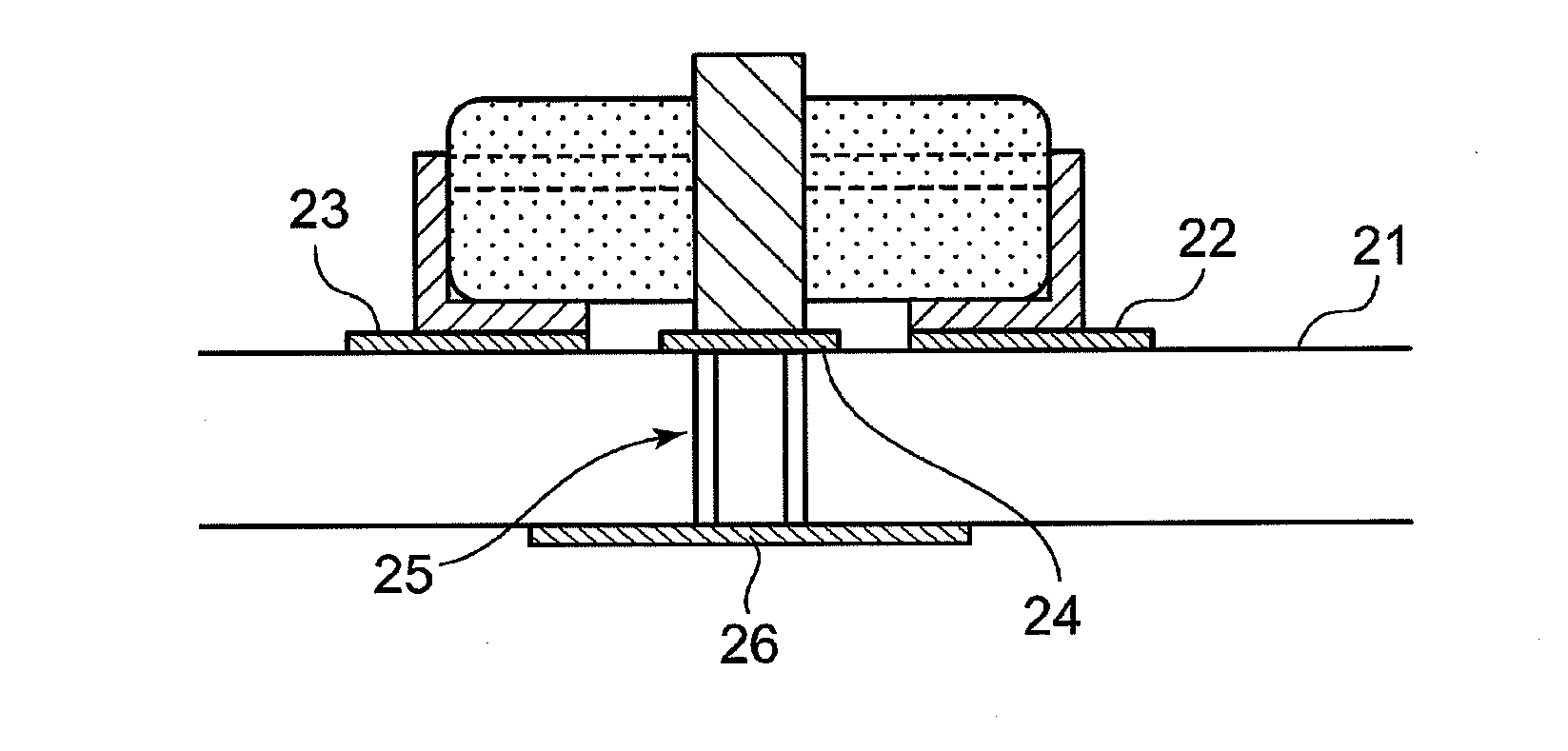
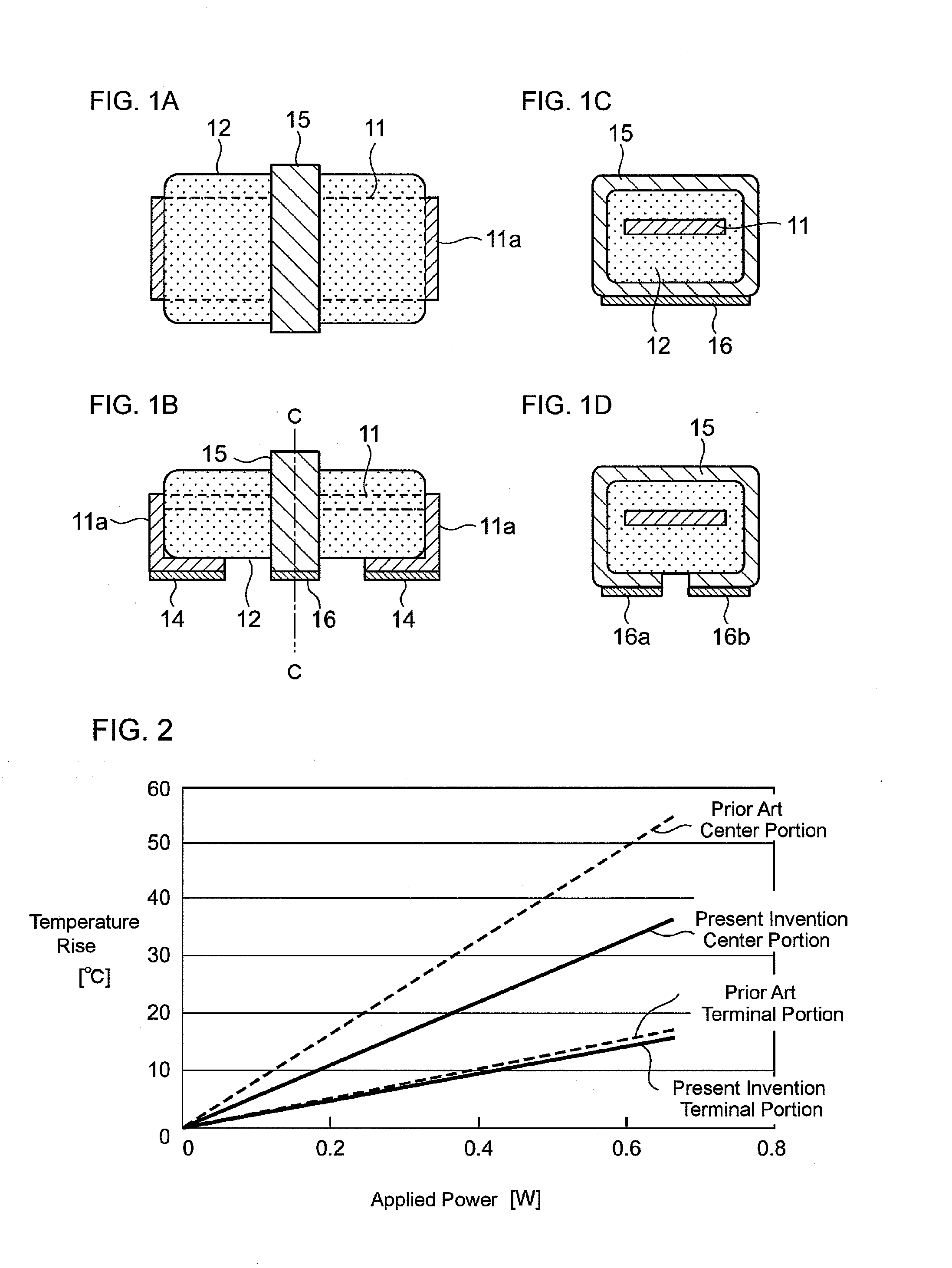
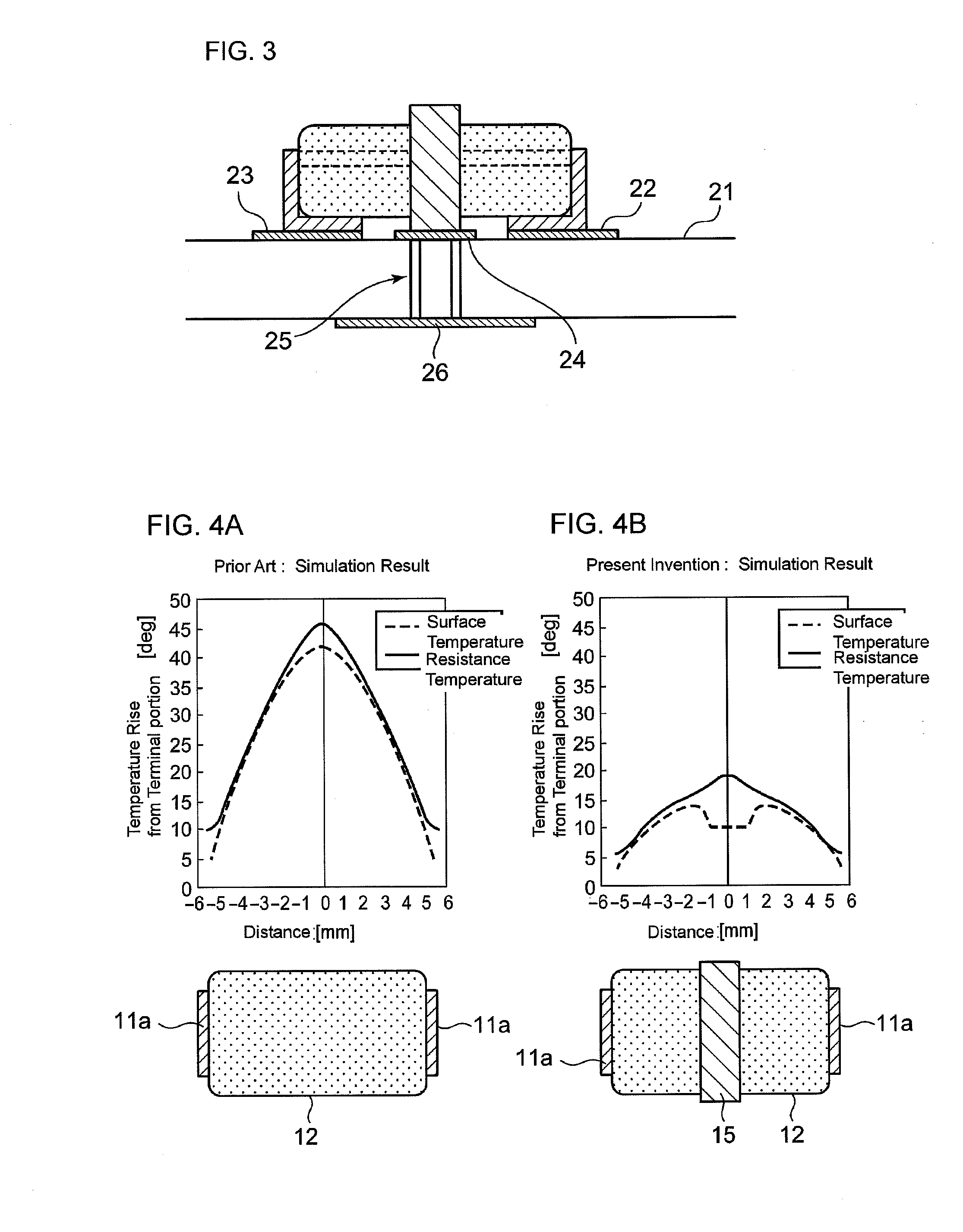
[0023]FIGS. 1A-1D show a resistor device of the present invention. The resistor device is a metal plate resistor device for current detection, in which a portion of resistive plate 11 of metal plate material such as Cu—Ni alloy etc. used as a resistance body is sealed by resin. The portion of resistive plate 11 enclosed by molded resin body 12 works substantially as the resistance body, and another portions of resistive plate 11 extending from the molded resin body 12 become terminal portions 11a. Both terminal portions 11a are bent along longitudinal end face and bottom face of the molded resin body 12. The terminal portion 11a of resistive plate 11 is provided with solder layer 14 at bottom face of the molded resin body 12. The solder layer 14 makes solder bondability to printed circuit board etc. good.

[0024]The radiative plate 15, which comprises metal plate material of good thermal conductivity such as Cu film or Cu plate etc., is disposed on outer faces of the molded resin bod...

second embodiment

[0036]Further, an example of the resistor device of second embodiment, which uses a resistive plate, has been explained. However, resin-sealed current-detecting resistor device, which comprises a resistive plate and metal terminal plates connected at both ends of the resistive plate shown in FIG. 5A, and another resin-sealed current-detecting resistor device, which comprises a thick film resistor shown in FIG. 5B, are also possible to adopt the buried radiative plate structure in molded resin body shown in FIGS. 6A-6D.

[0037]Next, manufacturing method of the resistor device will be explained referring to FIGS. 7A-7G. At first, as shown in FIG. 7A, a resistive plate of resistance alloy such as Cu—Ni alloy etc. is machined by press etc. to prepare strip-shaped metal resistive plate 31, which includes resistive plate 11 and has the shape shown in the view. Strip-shaped plate 31 is provided with forwarding hole 31a for forward processing by automatic machine, and the structure is suitabl...

third embodiment

[0041]Next, a resistor device of third embodiment of the present invention will be described with referring to FIGS. 8A-8G. The resistor device is relating to various kinds of resistor devices including circle stick type leaded resistors such as metal film resistors, metal oxide film resistors, wire wound resistors, metal glaze resistors, and ceramic resistors. The resistor device is formed by sealing these resistors into rectangular-shaped molded resin body, disposing a portion of radiative plate above resistance body inside of molded resin body, and disposing terminal portions of radiative plate and resistive plate so that they are bent along side face, end face, and bottom face of the molded resin body so as to be surface-mountable.

[0042]An example of manufacturing process is, at first, as shown in FIG. 8A, to prepare a circle stick type leaded resistor 33, which is provided with main body of resistor 33a and lead terminal 33b. Next step is, as shown in FIG. 8B, to carry out firs...


PUM

PropertyMeasurementUnit
Poweraaaaaaaaaa
Sizeaaaaaaaaaa
Shapeaaaaaaaaaa

Abstract

The resistor device is provided with a resistive plate (11) of metal plate material, which is used as a resistance body; a radiative plate (15) of metal plate material, which is spaced from the resistive plate and intercrossed on the resistive plate; a molded resin body (19), which encloses an intercrossing portion of the resistive plate and the radiative plate; terminal portions of the resistive plate (11a), which comprises so that both ends of the resistive plate extending from the molded resin body are bent along an end face and a bottom face of the molded resin body; and terminal portions of the radiative plate (15a), which comprises so that both ends of the radiative plate extending from the molded resin body are bent along an end face and a bottom face of the molded resin body. Accordingly, the surface-mountable resin-sealed metal plate resistor device is enabled to increase the power capacity drastically and to improve the reliability without changing most of the size.

Description

TECHNICAL FIELD[0001]The present invention relates to a surface-mountable resin-sealed resistor device, especially relating to a mounting structure for its heat dissipation.BACKGROUND ART[0002]Heretofore, upon an electronic part, which is surface-mountable on a printed circuit board etc., kinds of heat dissipation structures have been proposed by US patent publication 7148554, and Japanese laid open patent publications 2-309602, 8-181001, 5-217713, and 11-251103 etc.[0003]By US patent publication 7148554 and Japanese laid open patent publication 2-309602, it is proposed that forming an electrode for heat dissipation at central portion on bottom face of a ceramics substrate of rectangular chip resistor etc. to be spaced from resistor's electrodes, fixing heat dissipating electrode to a conductor pattern for cooling formed on a mounting board such as printed circuit board etc., and dissipating the heats. However, since the heat dissipating electrode is disposed at bottom face of the c...

Claims


Application Information

Patent Timeline
IPC IPC(8): H01C1/02H01C17/02
CPCH01C1/028H01C1/084H01C1/14H01C7/003Y10T29/49087H05K3/341H05K2201/10636H05K2201/10969Y10T29/49083H05K1/0203Y02P70/50
Inventor HIRASAWA, KOICHIAMEMIYA, HITOSHIHAYASHI, ATSUNORI
Owner KOA CORP
Why Eureka
Try Eureka