

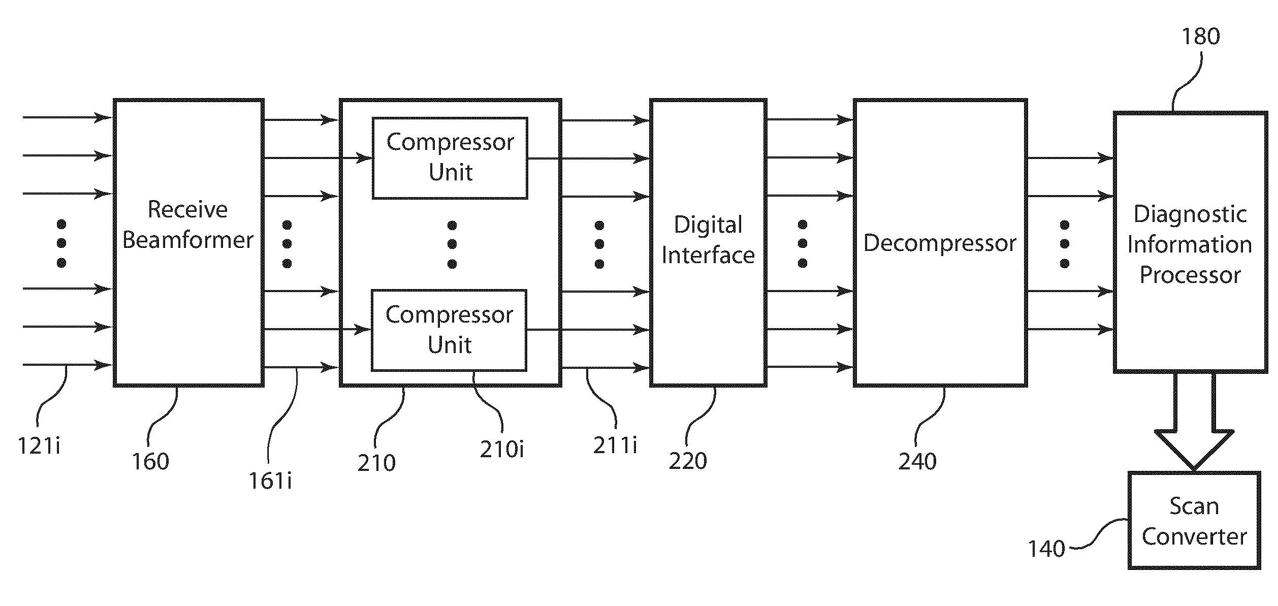
Post-beamforming compression in ultrasound systems
a compression and ultrasound technology, applied in the field of compression of beamformed samples, can solve the problems of reducing the storage capacity needed in the mass memory device, yaegashi does not disclose the beamforming in the processing sequence, and compression may be lossless or lossy, so as to reduce the storage capacity required for storing compressed beamformed samples, computationally efficient compression and decompression
- Summary
- Abstract
- Description
- Claims
- Application Information
AI Technical Summary
Benefits of technology
Problems solved by technology
Method used
Image

Examples
Embodiment Construction
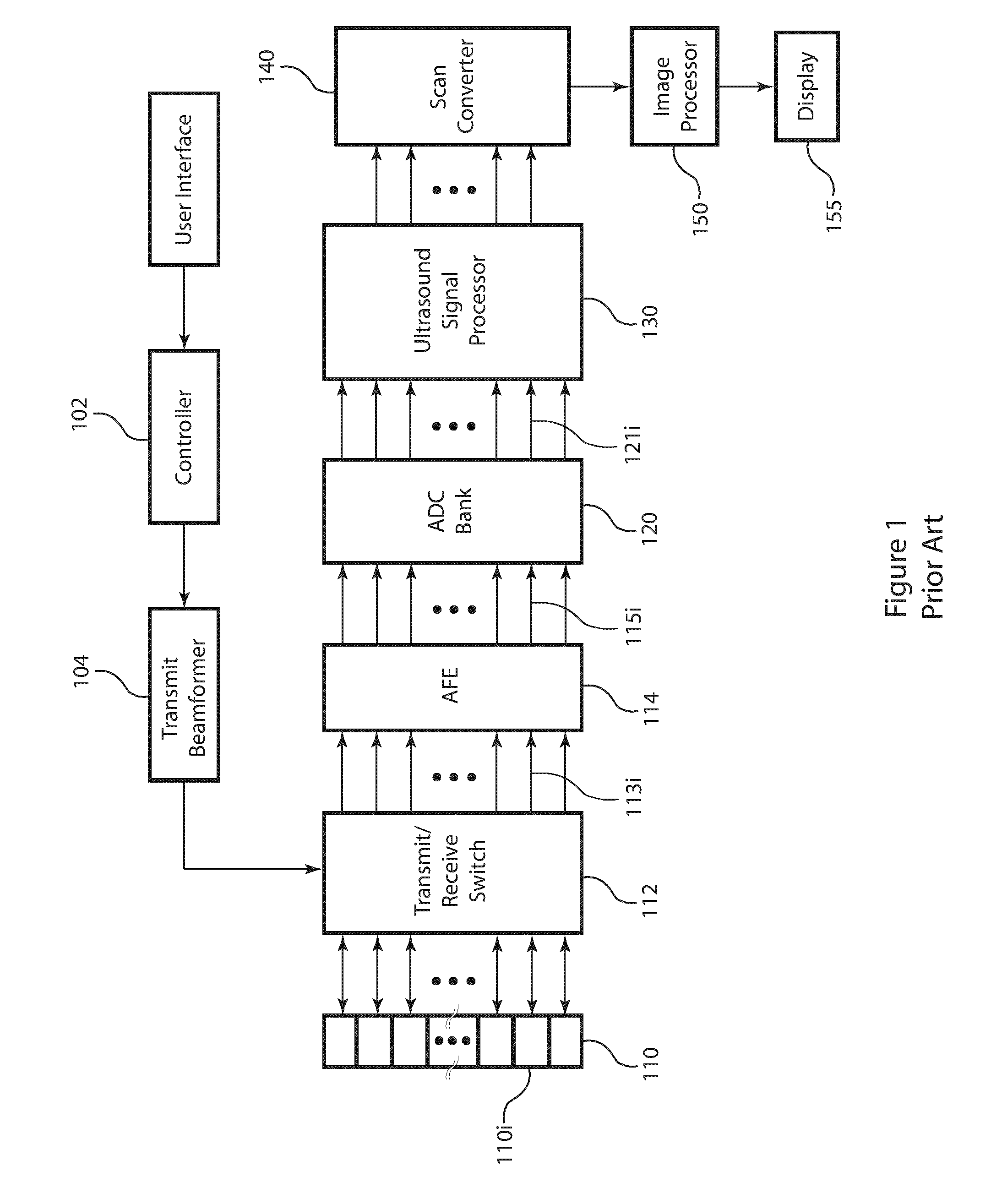
[0049]FIG. 1 is a block diagram of an example of a typical medical ultrasound system in accordance with the prior art. The transmit beamformer 104 is of a construction known in the art, such as a digital or analog beamformer. The transmit beamformer 104 generates one or more excitation signals in response to the system controller 102. The excitation signal has an associated center frequency, typically in the 1 to 20 MHz range. The excitation signals from the transmit beamformer 104 are provided to the ultrasound transducer 110 via the transmit / receive switch 112. The ultrasound transducer 110 comprises an array of transducer elements 110i. The ultrasound transducer 110 is of a construction known in the art that enables the coupling the ultrasound waves to the subject being examined. The transducer elements 110i both launch and receive ultrasound waves. The transmit / receive switch 112 includes the switching circuitry for transmit and receive modes. For transmit mode, the transmit / rec...
PUM
 Abstract
Description
Claims
Application Information