

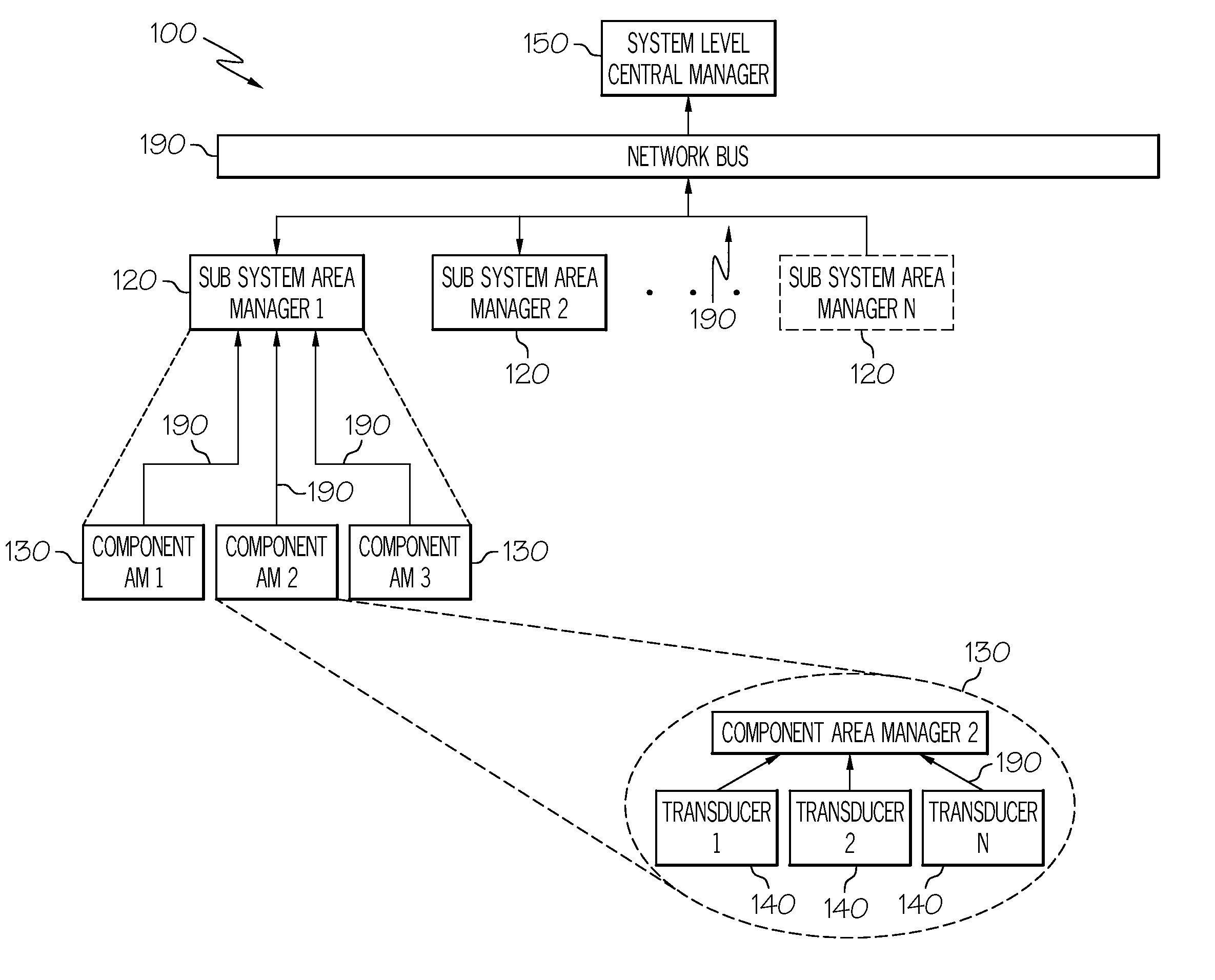
Vehicle system monitoring and communications architecture
a technology of vehicle system and communications architecture, applied in adaptive control, program control, instruments, etc., can solve the problems of increasing the computing power of the central computing device and the limited bandwidth of the installed data bus, increasing the cost of adding additional bandwidth, and potentially disruptive, and other complexities may arise at the central computing devi
- Summary
- Abstract
- Description
- Claims
- Application Information
AI Technical Summary
Benefits of technology
Problems solved by technology
Method used
Image

Examples
Embodiment Construction
[0015]The following detailed description of the invention is merely exemplary in nature and is not intended to limit the invention or the application and uses of the invention. Furthermore, there is no intention to be bound by any theory presented in the preceding background of the invention or the following detailed description of the invention.
[0016]The subject matter now will be described more fully below with reference to the attached drawings which are illustrative of various embodiments disclosed herein. Like numbers refer to like objects throughout the following disclosure. The attached drawings have been simplified to clarify the understanding of the systems, devices and methods disclosed. The subject matter may be embodied in a variety of forms. The exemplary configurations and descriptions, infra, are provided to more fully convey the subject matter disclosed herein.
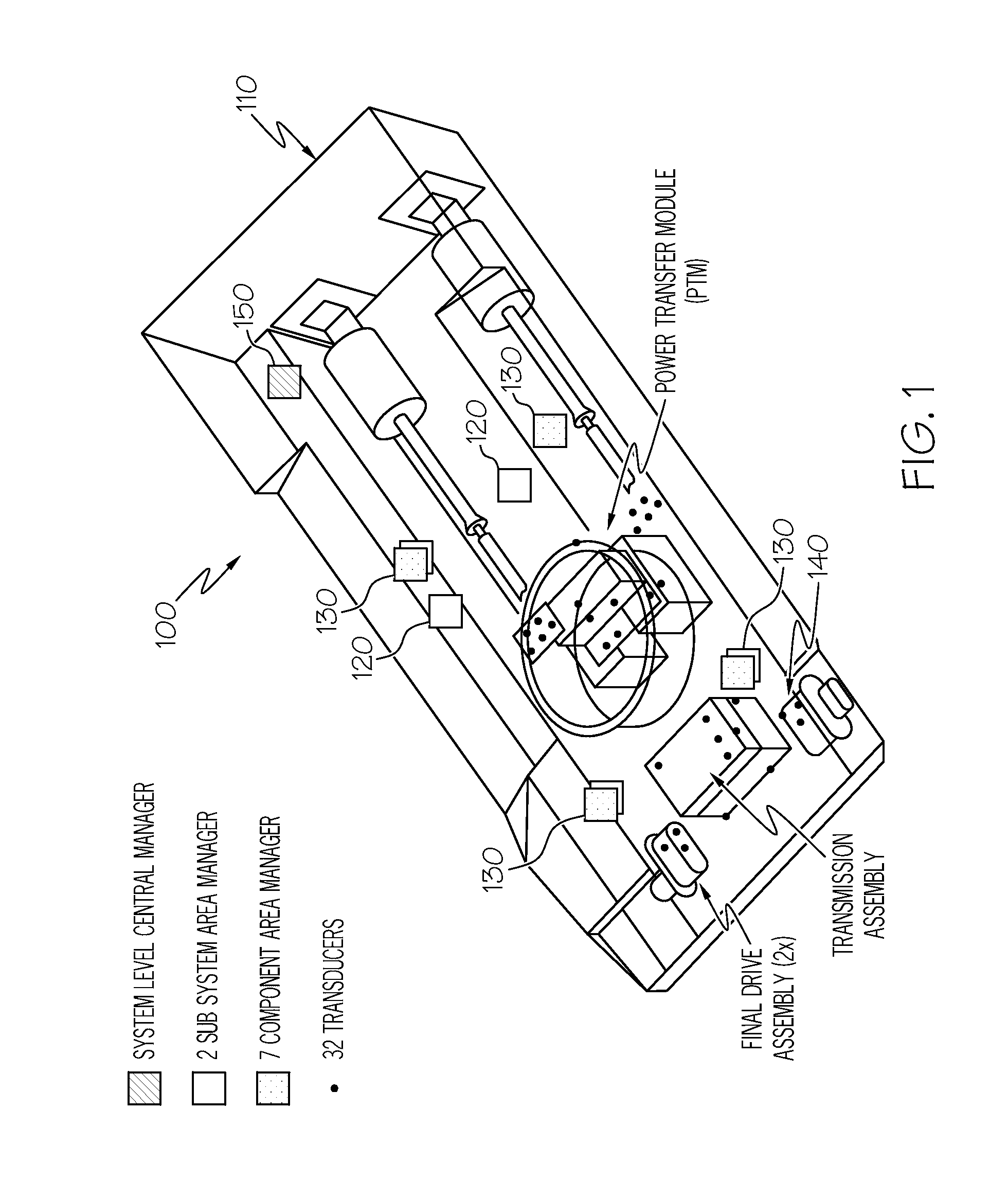
[0017]The subject matter herein will be disclosed below in the context of an amphibious assault vehicle. How...
PUM
 Abstract
Description
Claims
Application Information