Extended main memory hierarchy having flash memory for page fault handling

a page fault and memory hierarchy technology, applied in the field of memory organization in computer systems, can solve the problems of page fault generation, significantly greater latency of miss penalty incurred resulting from page fault, and achieve the effect of significantly reducing performance penalty associated with page faul

Active Publication Date: 2010-12-30
SUN MICROSYSTEMS INC
View PDF10 Cites 61 Cited by
  • Summary
  • Abstract
  • Description
  • Claims
  • Application Information

AI Technical Summary

Benefits of technology

[0011]In general, a system and method of operating the system are contemplated wherein flash memory is incorporated into the main memory hierarchy. The flash memory may be separate from flash memory that may be used to implement a solid state disk (SSD) in the I / O hierarchy (or any device in the I / O hierarchy). For a virtual address space having a plurality of pages, some (if not all) of the pages may be stored in the flash memory, with certain ones of the pages being stored in main memory as needed. When a page containing data requested by a processor or execution core is not stored in main memory, thereby causing a page fault, a memory management unit may respond by retrieving the particular page from the flash memory, without invoking an I / O driver to access the page from storage, and furthermore, without generating an interrupt to a processor or execution core. Since the memory management unit may handle the page fault without invoking an I / O driver to access storage in the I / O hierarchy, or without generating an interrupt, the performance penalty associated with the page fault may be significantly reduced, even if the system utilizes an SSD instead of a traditional hard disk drive.

Problems solved by technology

On the other hand, if the search of the page table or TSB does not find a valid address (indicating that the page does not reside in main memory), an exception known as a page fault may be generated.
Accordingly, the miss penalty incurred resulting from a page fault may have a significantly greater latency than for accesses to data from memory (or a higher level cache) where no page fault occurs.

Method used


Image

  • Extended main memory hierarchy having flash memory for page fault handling
  • Extended main memory hierarchy having flash memory for page fault handling
  • Extended main memory hierarchy having flash memory for page fault handling

Examples


Embodiment Construction

[0022]As a preliminary note, references to the term “data” as used herein are intended to include any type of binary information. For example, data may refer to data used as operands in execution of an instruction, result data generated from the execution of instructions, and / or the instructions themselves. The term “data” may also encompass various types of tags, bits, and so forth that are used to indicate attributes of other types of binary information. In general, the term “data” as used herein may refer to any type of binary information that may be stored, transferred, or operated on in a computer or other type of digital system.

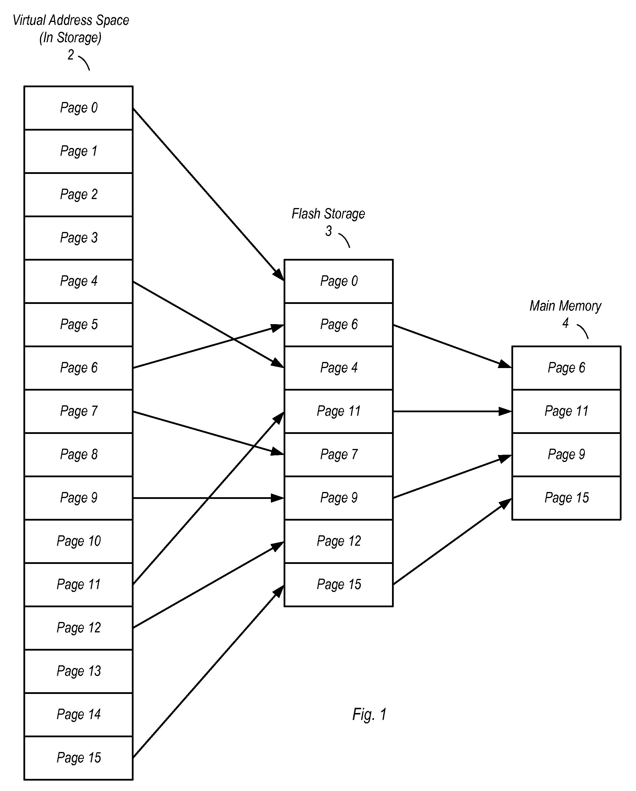
[0023]Turning now to FIG. 1, a diagram illustrating a paging scheme for one embodiment of a computer system is shown. In the embodiment shown, a virtual address space 2 used to augment a main memory 4 is shown as having a plurality of pages, i.e. page 0-page 15. The number of pages of virtual address space 2 may vary from one embodiment to the next, and...


PUM


Abstract

A computer system with flash memory in the main memory hierarchy is disclosed. In an embodiment, the computer system includes at least one processor, a memory management unit coupled to the at least one processor, and a random access memory (RAM) coupled to the memory management unit. The computer system may also include a flash memory coupled to the memory management unit, wherein the computer system is configured to store at least a subset of a plurality of pages in the flash memory during operation. Responsive to a page fault, the memory management unit may determine, without invoking an I/O driver, if a requested page associated with the page fault is stored in the flash memory and further configured to, if the page is stored in the flash memory, transfer the page into RAM.

Description

BACKGROUND OF THE INVENTION[0001]1. Field of the Invention[0002]This invention relates to computer systems, and more particularly, to memory organization in computer systems.[0003]2. Description of the Related Art[0004]Because memory space in computer systems is limited while the desire for memory space is unlimited, various techniques may be employed to extend the apparent size of a main memory in a given computer system. One such technique is the use of virtual memory, wherein main memory may be augmented with storage space on a disk. Moreover, certain virtual memory schemes may utilize overlays known as pages, wherein an address space may be partitioned into equal sized blocks. These blocks may be swapped between a disk storage system and main memory as needed during operation of a computer system. Some virtual memory schemes may also utilize segments, wherein blocks of an address space are partitioned into blocks of varying sizes.[0005]In computer systems using virtual memory, v...

Claims


Application Information

Patent Timeline
Patent Type & Authority Applications(United States)
IPC IPC(8): G06F12/00G06F12/02G06F12/10
CPCG06F12/08Y02B60/1225G06F2212/2022G06F12/10G06F2212/205Y02D10/00G06F2212/202
Inventor KAPIL, SANJIVHETHERINGTON, RICKY C.
Owner SUN MICROSYSTEMS INC
Why Eureka
Try Eureka