
Method for operating an internal combustion engine

a technology of internal combustion engine and internal combustion chamber, which is applied in the direction of combustion air/fuel air treatment, electric control, instruments, etc., can solve the problems of increased unfavorable compression of combustion air, so as to improve the response behavior of internal combustion engine and reduce the knocking tendency of internal combustion engine

Inactive Publication Date: 2011-01-06
ROBERT BOSCH GMBH
View PDF6 Cites 2 Cited by
  • Summary
  • Abstract
  • Description
  • Claims
  • Application Information

AI Technical Summary

Benefits of technology

[0005]Accordingly, it is an object of the present invention to provide a method for operating an internal combustion engine, by which the response behavior of the internal combustion engine is improved and a knocking tendency of the internal combustion engine is reduced.

Problems solved by technology

However, compression of the combustion air also goes hand in hand with an undesired increased knocking tendency of an internal combustion engine.

Method used


Image

  • Method for operating an internal combustion engine
  • Method for operating an internal combustion engine
  • Method for operating an internal combustion engine

Examples


Embodiment Construction

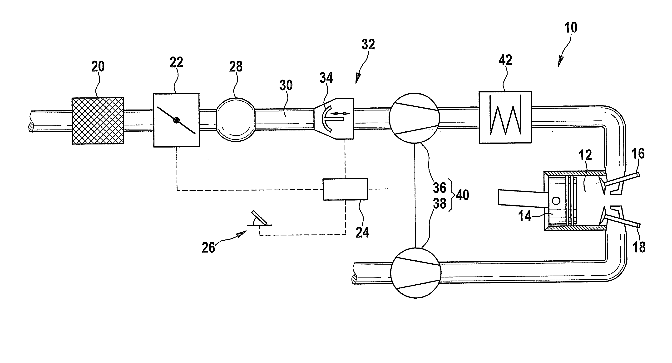
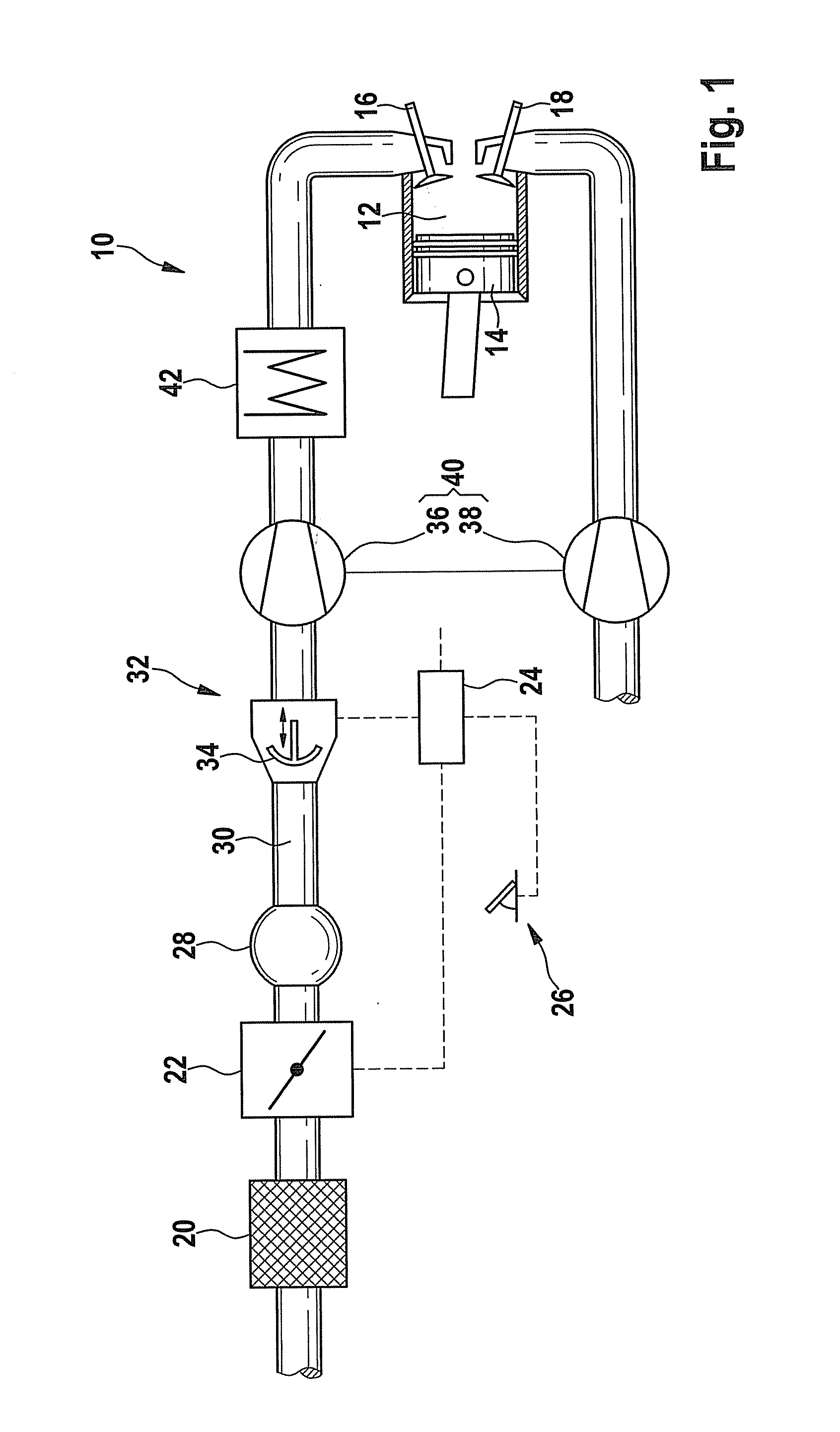
[0022]FIG. 1 shows a schematic representation of an internal combustion engine denoted by reference numeral 10 as a whole. Internal combustion engine 10 has at least one combustion chamber 12 inside which a piston 14 is moved up and down with the aid of a crankshaft (not shown). An intake valve 16 is provided in order to control combustion air that is introduced into combustion chamber 12. A discharge valve 18 is provided for controlling the exhaust gas discharged from combustion chamber 12.

[0023]Internal combustion engine 10 includes an air filter 20 for filtering fresh air. A throttle valve 22 is provided to control a filtered flow of fresh air. Throttle valve 22 is triggered with the aid of a control unit 24, which processes signals from a driver pedal 26 for this purpose.

[0024]Downstream from throttle valve 22 is a collection region 28, which terminates in an intake duct 30. Disposed in intake duct 30 is a pulse supercharger 32, which includes a pulse charging valve 34 by which ...


PUM


Abstract

A method for operating an internal combustion engine in which combustion air is supplied to a combustion chamber of the internal combustion engine, which air is compressed with the aid of a pulse supercharger, the pulse supercharger being controlled in such a way that optionally, in a first operating mode, the combustion air is compressed in order to support a compressor of a turbocharger, or in a second operating mode, the combustion air compressed with the aid of the compressor is cooled.

Description

FIELD OF THE INVENTION[0001]The present invention relates to a method for operating an internal combustion engine in which combustion air compressed with the aid of a pulse supercharger is supplied to a combustion engine of the internal combustion engine.[0002]Furthermore, the present invention relates to a computer program and a control unit for an internal combustion engine.BACKGROUND INFORMATION[0003]A pulse supercharger is used for closing the intake duct of an internal combustion engine during an intake contact, so that vacuum pressure is produced in the combustion chamber when a piston of the internal combustion engine is moving in the direction of bottom dead center. If the pulse supercharger is then opened suddenly, the aspirated air column is accelerated due to the vacuum pressure in the combustion chamber, so that a pulse-type pressure wave is created which penetrates into the combustion chamber. An escape of the overpressure wave is able to be prevented by timely closing ...

Claims


Application Information

Patent Timeline
Patent Type & Authority Applications(United States)
IPC IPC(8): F02D28/00F02B33/00
CPCF02B29/0406F02B29/083F02B33/446F02B37/00F02B37/004Y02T10/42F02D41/0002F02D41/0007Y02T10/146Y02T10/144F02D23/00Y02T10/12Y02T10/40
Inventor BAEUERLE, MICHAELKLENK, MARTINSIEBER, UDO
Owner ROBERT BOSCH GMBH
Learn More