
Methods and structures for sandwich panels with improved resistance to ballistic penetration

a sandwich panel and ballistic penetration technology, applied in the field of ballistic armor, can solve the problems of not being able to achieve the two separate functions of sandwich panel technology in an optimal weight fashion, poor impact strength out of plane, and barely slowing ballistic projectiles

Inactive Publication Date: 2011-01-13
MARYLAND AT BALTIMORE COUNTY UNIV OF
View PDF7 Cites 21 Cited by
  • Summary
  • Abstract
  • Description
  • Claims
  • Application Information

AI Technical Summary

Benefits of technology

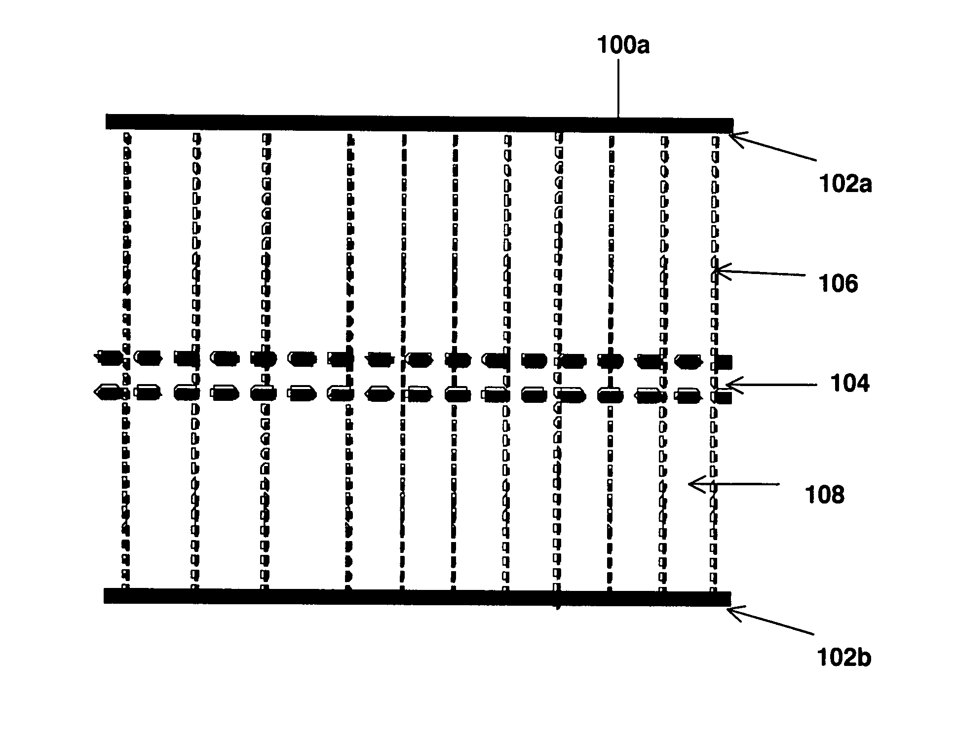
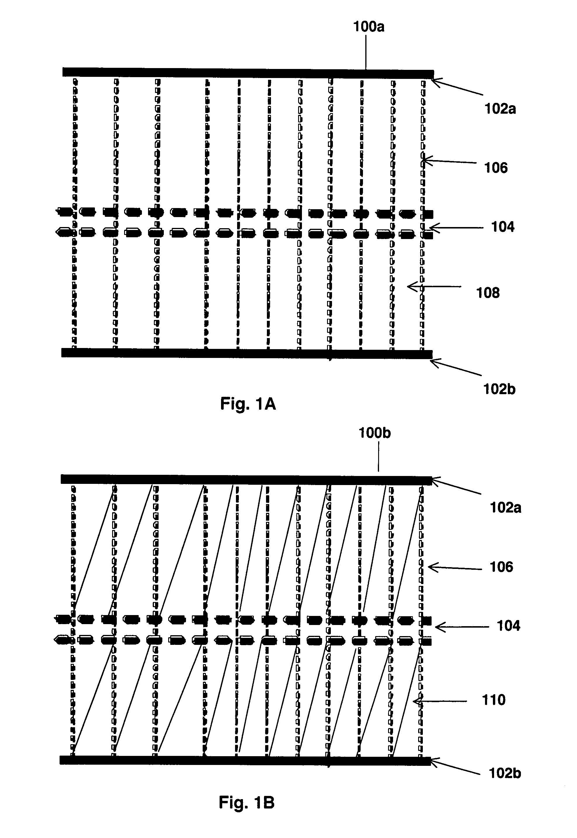
[0012]One objective of the present invention is to develop a structural sandwich panel that combines the high specific strength and stiffness of currently available sandwich construction materials with superior resistance to ballistic penetration. Another objective of the present invention is to develop a hybrid core or tooling material that can protect extremely weight sensitive structures, especially, but not limited to aerospace vehicle structures, that might otherwise remain unarmored.
[0013]Another objective of the invention is to provide ballistic resistance through an innovative combination of crushable or breakable sacrificial pins and an antiballistic fabric, encased within panels with the primary conventional function of providing structural support to a vehicle. Another objective of the present invention is to prevent through penetration by a focused ballistic threat without greatly increasing the weight of the structure by providing sufficient open interior space to allow the absorption and dissipation of substantial amounts of strain energy prior to allowing the projectile to make contact with the rear face sheet.

Problems solved by technology

However, a notable weakness of the existing sandwich panels is that out-of-plane impact strength is very poor and can barely slow a ballistic projectile.
For this reason, existing sandwich panel technology can not achieve these two separate functions in a weight optimal fashion.
Specifically, the prior art is deficient in sandwich panels that would absorb the impact energy of projectiles while minimally compromising payload capacity.

Method used


Image

  • Methods and structures for sandwich panels with improved resistance to ballistic penetration
  • Methods and structures for sandwich panels with improved resistance to ballistic penetration
  • Methods and structures for sandwich panels with improved resistance to ballistic penetration

Examples


Embodiment Construction

[0023]As used herein, the term “a” or “an” when used in conjunction with the term “comprising” in the claims and / or the specification may mean “one,” but it is also consistent with the meaning of “one or more,”“at least one,” and “one or more than one.” As used herein, the term “or” in the claims is used to mean “and / or” unless explicitly indicated to refer to alternatives only or the alternatives are mutually exclusive, although the disclosure supports a definition that refers to only alternatives and “and / or.”

[0024]As used herein, the terms “rigid face sheet”, “skin” and “face sheet” are intended to be interchangeable.

[0025]As used herein, the terms “pins” or “sacrificial pins” refer to relatively slender solid or hollow pins, headed or un-headed nails, rods, other rod- or truss-like members and any equivalent structures known in the art. The pins used in different embodiments are chosen such that they are either deformable, breakable or crushable upon impact and because of this p...


PUM

PropertyMeasurementUnit
anglesaaaaaaaaaa
diameteraaaaaaaaaa
thicknessaaaaaaaaaa

Abstract

Provided herein methods and structures for construction of light weight sandwich panels or load-bearing panels having improved ballistic protection. The methods disclosed can facilitate construction of a hybrid core comprising ballistic fabrics and deformable pins that exhibit superior resistance to ballistic penetration. The methods and structures of the present disclosures can be advantageously used in many applications, such as armored vehicles.

Description

CROSS-REFERENCE TO RELATED APPLICATION[0001]This non-provisional application claims benefit of priority of provisional U.S. Ser. No. 60 / 796,603, filed May 1, 2006, now abandoned.BACKGROUND OF THE INVENTION[0002]1. Field of Invention[0003]The present invention relates to the fields of ballistic armor for lightweight structures including aerospace vehicles and for sandwich panel construction techniques. More specifically, the present invention relates to methods and structures for sandwich panel construction that provide improved resistance to ballistic penetration.[0004]2. Description of the Related Art[0005]Sandwich panels have been used widely in all types of situations where light weight and high structural strength are required. Sandwich panels have been used extensively in the aerospace industry. For example, sandwich panels are used in aircraft structural parts and control surfaces as well as cabin floors and other interior panels. Sandwich panels could be, but are not yet gene...

Claims


Application Information

Patent Timeline
Patent Type & Authority Applications(United States)
IPC IPC(8): F41H5/04B32B3/10B32B3/12B32B7/08F41H7/02B64D7/00B64G1/52
CPCB64D7/00B64D37/32B64G1/56Y10T428/24149F41H5/0471Y02T50/44Y10T428/24331F41H5/023Y02T50/40
Inventor FARQUHAR, TONYMARLOWE, RICHARD BRIAN
Owner MARYLAND AT BALTIMORE COUNTY UNIV OF
Learn More