
Method of actuating a switch between a device and a power supply

Inactive Publication Date: 2011-01-13
KONINKLIJKE PHILIPS ELECTRONICS NV
View PDF8 Cites 7 Cited by
  • Summary
  • Abstract
  • Description
  • Claims
  • Application Information

AI Technical Summary

Benefits of technology

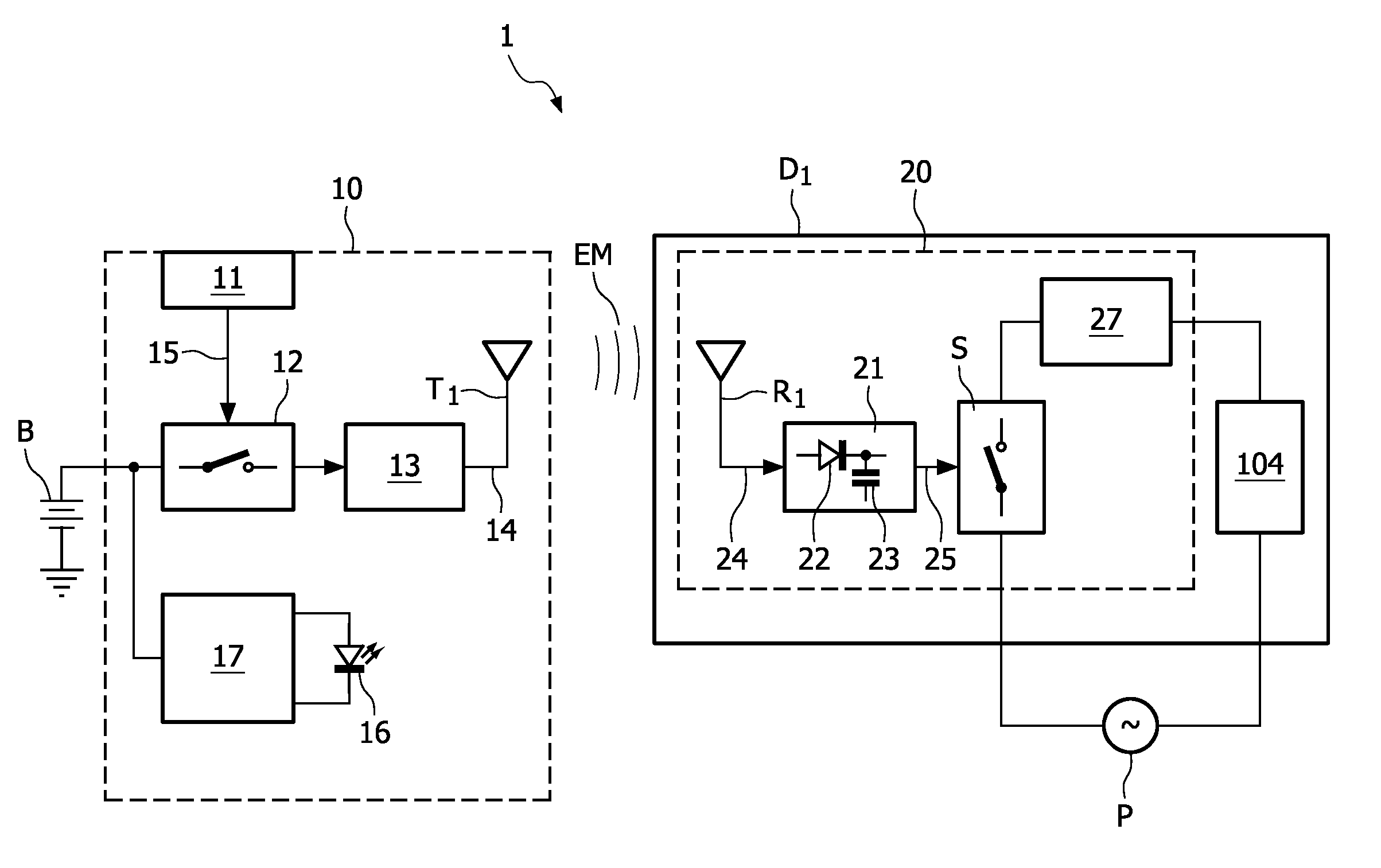
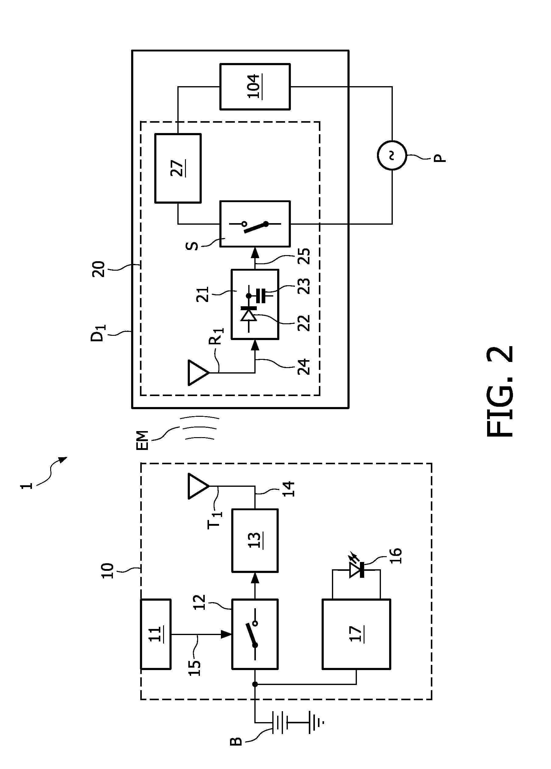
[0008]In the method according to the invention, the electromagnetic radiation is automatically detected in an entirely passive manner by the detecting antenna, which is caused to resonate by the energy in the electromagnetic radiation, giving the second electrical signal. Also, the conversion of this AC electrical signal into a DC switch actuating signal is performed in an entirely passive manner, i.e. by using electrical components that do not require a power supply. An obvious advantage of the method according to the invention is that, when a device is turned off in the manner described, it is indeed off, and not merely in standby. The device is entirely quiescent when turned off using this method, since it does not draw any current and does not consume any power. An obvious advantage of the method according to the invention is the saving in energy that can be obtained. Another further advantage is that the device can still be reactivated by the remote control, so that convenience and ease of use are not compromised in any way.
[0016]The first electrical signal can be continuously generated, i.e. as a continuous signal without interruption. In a preferred embodiment of the invention, the first electrical signal comprises a pulsed high-frequency signal, i.e. the signal generator outputs a series of high-frequency pulses, perhaps with the aid of a suitable capacitor, as will be know to a person skilled in the art. One advantage of this technique is that the lifespan of a battery powering the signal generator is prolonged. More importantly, pulsing allows the energy, i.e. the amplitude, of the first electrical signal to effectively be increased, so that the reliability of the switching process is improved. At the same time, it can be ensured that an overall average energy value of the signal is not exceeded, so that the signal satisfies safety standards. Also, this technique allows the signal range to be increased. Again, the signal generated in this way can be of a predefined duration, or may be generated as long as the user carries out the appropriate action with the remote control device.
[0018]A high-frequency signal in an ISM band can be used to carry information which can be decoded at the receiving end. Therefore, in a further preferred embodiment of the invention, the first electrical signal comprises a carrier signal modulated to carry device identification information, such as a device identification code, for the device to be controlled. This can be advantageous when several devices are controlled by remote control units using the method according to the invention, or, more particularly, when a single remote control unit is used to control more than one device. In such a case, the remote control unit can be equipped with different buttons for addressing the different devices, and for each device activated or deactivated with this remote control, the actuating switch is opened or closed on the basis of the device identification information. This will be explained in more detail in conjunction with the description of the figures. The actuating switch in the remote control interface module of a device can be a simple toggle switch, so that the actuating signal causes the switch to be closed if it was already opened, and opened if it was already closed.
[0020]In a preferred embodiment of the invention, the remote control interface module is incorporated in the device to be controlled. Advantageously, the remote control interface module described above can act as a preliminary stage for a state of the art remote control interface, since the user can control the device in the usual remote control manner once the device is activated from its quiescent state using one of the methods described above. Since the components required for the remote control interface module are small and inexpensive, a device such as a television or receiver can easily be adapted to include a remote control interface module according to the invention. Adaptation can take place during the manufacturing process, but it also conceivable that an already existing device could be modified to include the type of remote control interface module disclosed here. Equally, a remote control interface module for an existing device could be placed between the device and its power supply, for example between the mains plug of the device and an electrical socket.
[0021]A pair of antennae, one each in remote control unit and remote control interface module, is generally sufficient for a simple function such as toggling between an ‘on’ state and an ‘off’ state as already described above. However, the method according to the invention could also be used for more advanced functions such as increasing or decreasing the brightness of a light source that avails of a remote control interface unit. This can be achieved by generating the signal at distinct frequencies in the remote control unit, for example at a first frequency for an ‘on’ function, or at a second, different, frequency for an ‘off’ function. At the receive side, corresponding filters, responsive to the first or second frequency, can determine the intended function.

Problems solved by technology

Usually, the standby power is quite low, only a few watts, but particularly inefficient devices can consume up to 20 watts in standby mode.
Since almost every household or office has several devices that are ‘turned off’ by placing them in standby mode, the total amount of standby power dissipated by the millions of devices around the globe is actually quite considerable.
However, this approach still involves some amount of power dissipation for the required current monitoring components, for instance a power supply for a timer circuit.
Also, a certain amount of time should be allowed to elapse before actually disconnecting the device, and during this time, standby power is consumed.

Method used


Image

  • Method of actuating a switch between a device and a power supply
  • Method of actuating a switch between a device and a power supply
  • Method of actuating a switch between a device and a power supply

Examples


Embodiment Construction

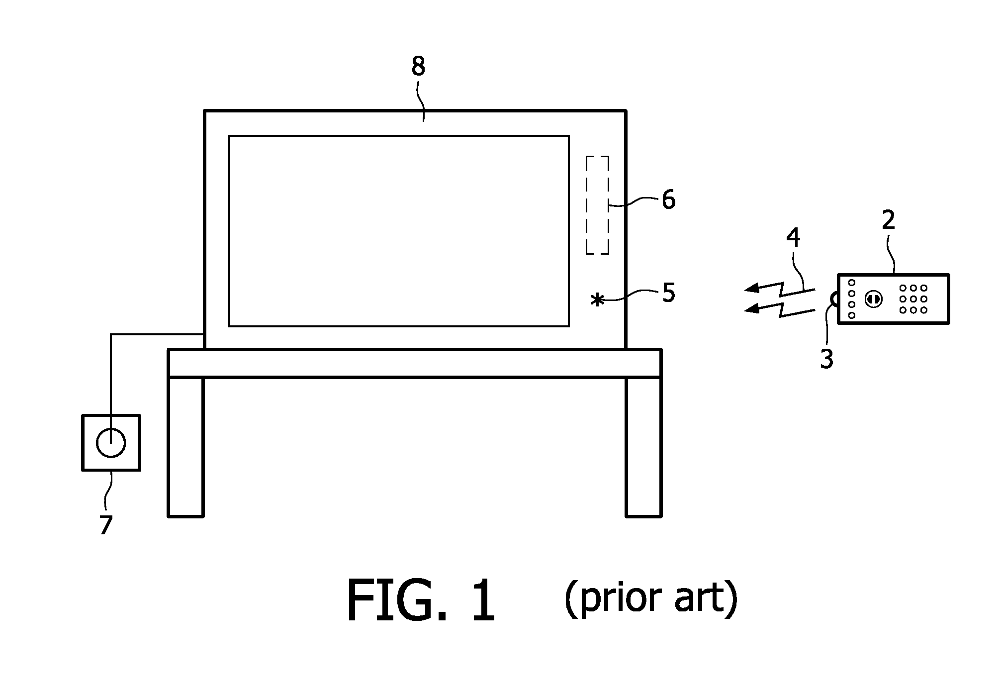
[0047]FIG. 1 shows a state of the art situation with a remote controllable device 8, in this case a television, and a remote control unit 2, which is usually operated by a user (not shown) at a distance from the device 8. The user presses certain buttons on the remote control unit 2 to turn the device 8 on, change device settings, for example to change channels or to adjust the loudspeaker volume, or to place the device 8 in a standby mode. The state of the art remote control unit 2 shown operates by generating an infrared control signal 4 by means of an infrared diode 3. When the remote control 2 is directed at the device 8, the control signals 4 can be detected by a suitable interface 6 in the device 8, and converted into appropriate device control signals. The device 8 draws current from a power supply, indicated in the diagram by the mains socket 7. When in standby mode, the device 8 is not completely disconnected from the mains power, since the interface 6 requires a small amou...


PUM


Abstract

The invention describes a method of actuating a switch (S) between a device (Di) to be controlled and a power supply (P), which method comprises the steps of generating a first electrical signal (14) in a remote control unit (10) and converting the first electrical signal (14) into electromagnetic radiation (EM) by means of a first transmitting antenna (Ti) of the remote control unit (10). A first detecting antenna (Ri) of a remote control interface module (20) of the device (Di) to be controlled detects the electromagnetic radiation (EM) to obtain a second electrical signal (24), which is passively converted into a switch actuating signal (25). The switch actuating signal (25) is actuated to switch the device (Di) to be controlled between an operating mode in which current is drawn from the power supply (P) by the device (Di) during operation, and an inactive mode in which the device (Di) is completely disconnected from the power supply (P) so that no current is drawn by the device (Di). The invention further describes a system (1) for actuating a switch (S) between a device (Di) to be controlled and a power supply (P). The invention also describes a remote control interface module (20) and a remote control unit (10).

Description

FIELD OF THE INVENTION[0001]The invention describes a method of actuating a switch between a device to be controlled and a power supply. The invention also describes a system for actuating a switch between a device to be controlled and a power supply. The invention further describes a remote control interface unit and a remote control device.BACKGROUND OF THE INVENTION[0002]Almost every consumer electronics device available today features a so-called standby mode of operation so that the device, even when turned ‘off’, is still receptive to control signals. The device can react at any time to a signal sent by a remote control unit to turn the device on again. Examples of such devices are televisions, satellite receivers, air-conditioners, video recorders, tuners, personal computers, etc. Usually, an easily visible ‘standby’ LED indicates to the user that the device is in standby mode. Being able to place a device in standby is generally regarded as practical and convenient, compared...

Claims


Application Information

Patent Timeline
IPC IPC(8): H01H9/54
CPCG08C17/02G08C2201/12G08C2201/10
Inventor HILGERS, ACHIM
Owner KONINKLIJKE PHILIPS ELECTRONICS NV
Learn More