Method and Apparatus for Microscopy

a microscopy and apparatus technology, applied in the field of apparatus and microscopy apparatus, can solve the problems of slow and trial-error process of orienting embryos, high time-consuming switching from one embryo to another, and inability to commercialize rotational stages, etc., and achieve the effect of fast orientation

Active Publication Date: 2011-01-13
SUZHOU BOUNDLESS MEDICAL TECH CO LTD
View PDF10 Cites 6 Cited by
  • Summary
  • Abstract
  • Description
  • Claims
  • Application Information

AI Technical Summary

Benefits of technology

[0015]In another aspect of the method of the present invention the microscopic means and the position control means are linked to a host computer, said host computer having control utility and image processing utility.
[0016]Advantages of the rotational orientation stage of the present invention include the fast orientation of samples of interest while keeping them within the

Problems solved by technology

Presently, such rotational stages are not commercially available, and there are no known studies/research on this topic in the literature.
Due to poor controllability, orienting embryos is a slow and trial-error process.
Furthermore, the use of a holding pipette makes switching from one embryo to another highly time-consuming.
The structures of these stages block the optical path, making them unsuitable for use on inverted microscopes

Method used


Image

  • Method and Apparatus for Microscopy
  • Method and Apparatus for Microscopy
  • Method and Apparatus for Microscopy

Examples


example 1

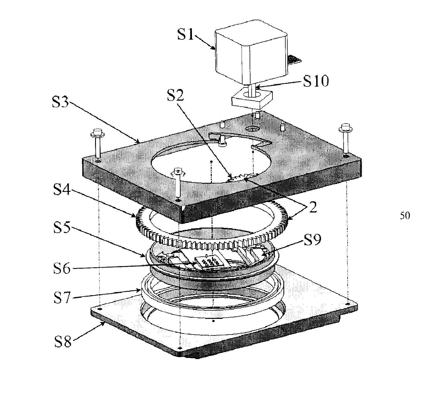
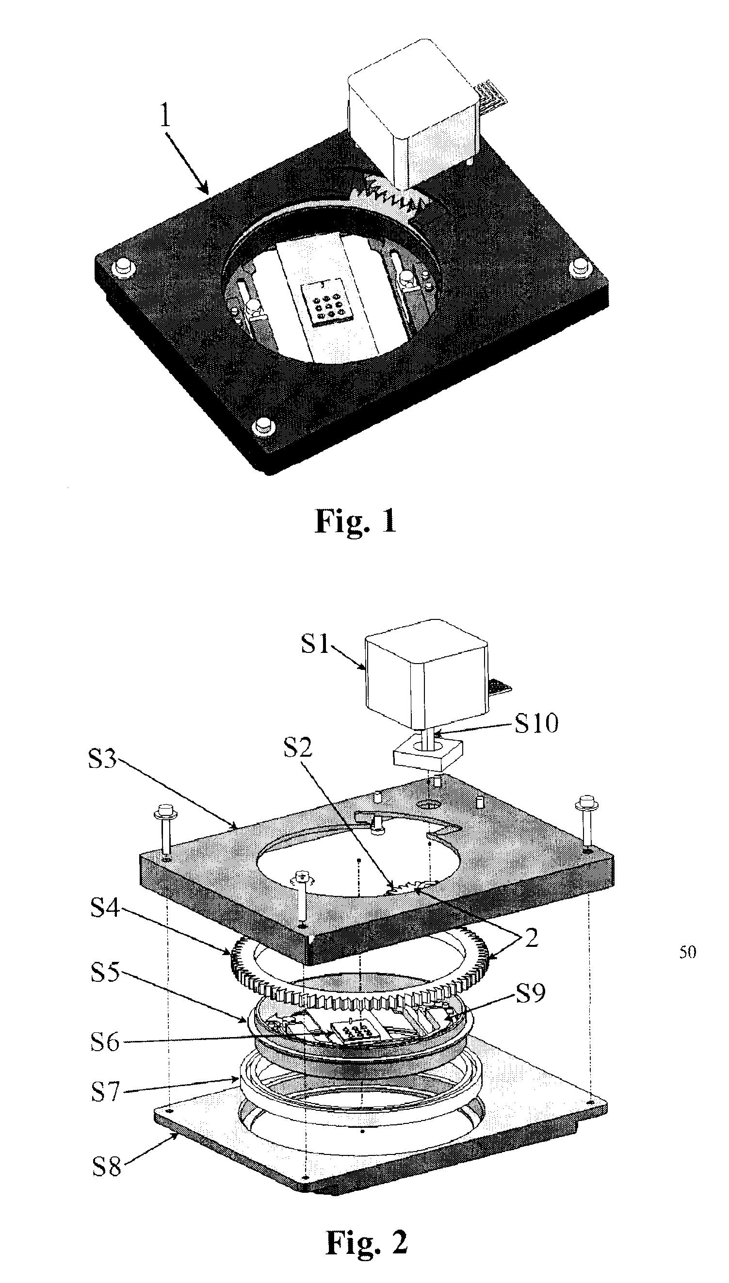
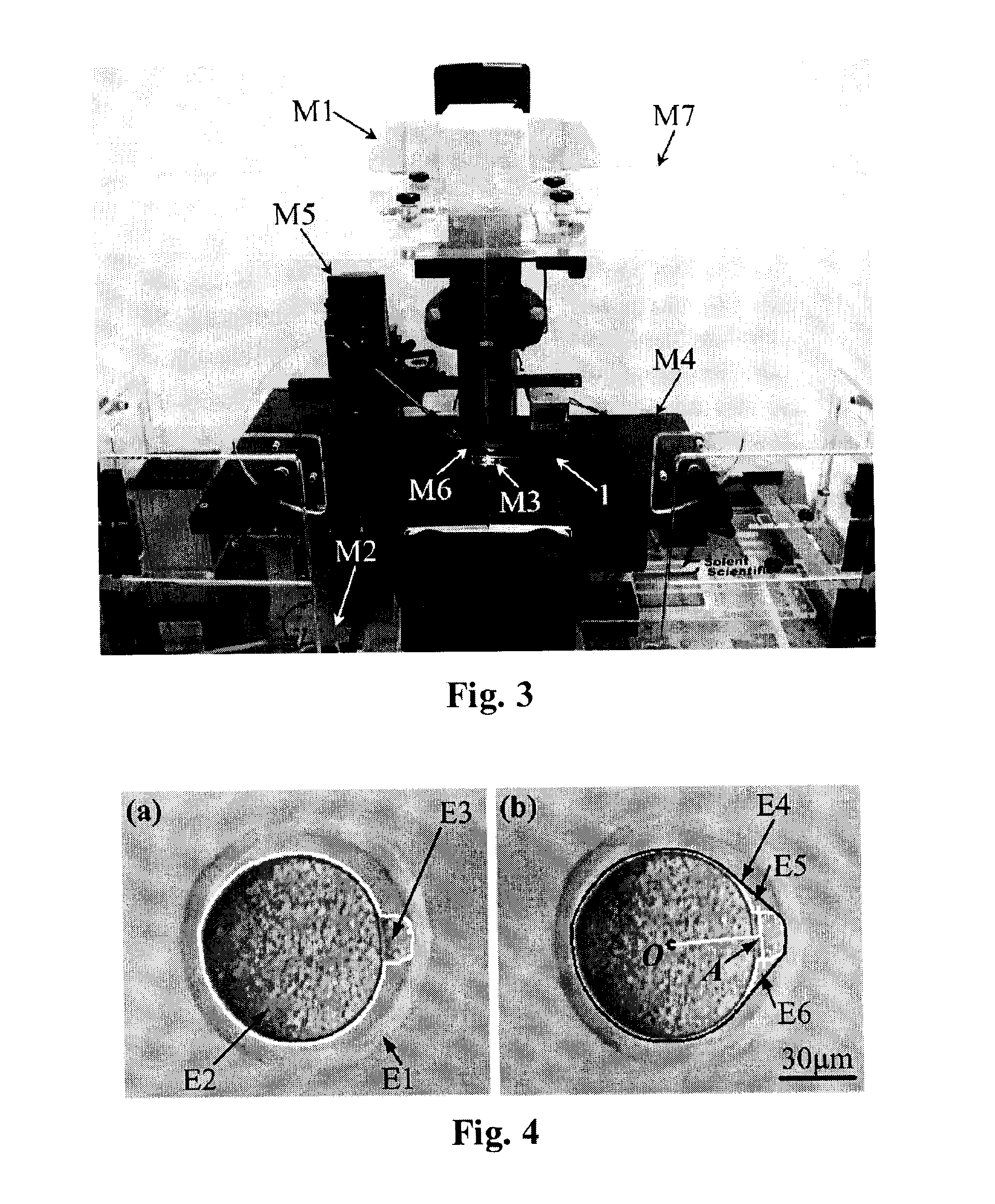
[0046]Materials: Mouse embryos used in the experiment were collected from ICR mice according to standard protocols approved by the Mount Sinai Hospital Animal Care Committee (Toronto). A 20× objective (NA 0.4) and Hoffman modulation contrast imaging were used for embryo observation. Nine embryos at 3 hr post-collection were automatically oriented by the assembly of FIG. 2.

[0047]Results: The image-based visual servo controller operates at 30 Hz for orienting the first embryo. Experimental trials demonstrate that the visual servo controller is capable of successfully keeping the target image patch inside the field of view at an orientation speed of 7° / second.

[0048]For coordinate transformation calibration, the first target embryo was rotated up to 30°. The complete calibration process took 4.3 sec. The closed-loop position controller is capable of orienting the rest of the embryos within the same batch at 720° / sec (vs. 7° / sec using image-based visual servoing on the first embryo).

[004...


PUM


Abstract

The present invention relates to a compact motorized rotational stage for microscopy applications and control methods for automated sample orientation/rotation. The rotational stage includes a motor, a rotational motion transmission mechanism, and a rotating sample holder for accommodating a holding device such as glass slides/Petri dishes of different sizes. Mouse embryos are used as an example to explain the control methods. A pattern recognition utility was developed for identifying mouse embryo structures. The transformation between the holding device rotational coordinate frame and the translational positioning stage coordinate frame is calibrated during image-based visual servo control. The polar body of an embryo is oriented through purely image-based visual servo control or through coordinate transformation and closed-loop position control.

Description

PRIORITY[0001]This application claims the benefit of U.S. Provisional Patent Application No. 61 / 036,247, filed 13 Mar. 2008.FIELD OF INVENTION[0002]The invention relates generally to an apparatus and method for microscopy. More particularly, the invention relates to an apparatus and method that enable the orientation of a sample item for microscopic examination or manipulation while keeping the sample within the field of view of a microscope.BACKGROUND OF THE INVENTION[0003]Techniques for imaging birefringent objects, such as birefringent molecule imaging (e.g., spindle) in biology and biomedical engineering, require rotational stages operating on inverted microscopes for orienting samples (e.g., biological cells) at a high speed, with a high accuracy, and in an automated manner. Presently, such rotational stages are not commercially available, and there are no known studies / research on this topic in the literature.[0004]Among several model organisms, the mouse is a popular animal w...

Claims


Application Information

Patent Timeline
IPC IPC(8): G02B21/26G05D3/12
CPCG02B21/26G05B19/232G05B2219/49368G05B19/351G05B2219/41346G05B19/291
Inventor SUN, YULIU, XINYU
Owner SUZHOU BOUNDLESS MEDICAL TECH CO LTD
Why Eureka
Try Eureka