Massive multi-core processor built with serial switching

Active Publication Date: 2011-01-13
AVAGO TECH INT SALES PTE LTD
View PDF4 Cites 40 Cited by
  • Summary
  • Abstract
  • Description
  • Claims
  • Application Information

AI Technical Summary

Benefits of technology

[0010]Accordingly, the present invention provides a multi-processor network device (e.g., a layer 4-7 application switch) having a scalable design that is built on a fabric of PCI Express switches. More specifically, a PCI Express switching fabric is used to connect a plurality of processing cores in the application layer. The number of processing cores that can be connected through the PCI Express switching fabric is substantially higher than the number of processing cores that can be connected in a conventional network switching device. By increasing the number of processing cores that can be implemented in a network switching device, the present

Problems solved by technology

However, it is also necessary to limit the power requirements of this same data center.
While increasing the operating frequency has been the preferred method to gain higher performance, this technique is no longer viable.
This is partly due to limitations in the power budgets of the network switching devices, as well as limitations in the power allowed in the data center environments wh

Method used


Image

  • Massive multi-core processor built with serial switching
  • Massive multi-core processor built with serial switching
  • Massive multi-core processor built with serial switching

Examples


Embodiment Construction

[0016]PCI Express (PCIe) is a computer expansion card interface format. PCIe is typically used to connect a motherboard to peripheral devices in a PC. Unlike previous computer expansion card interfaces, which implemented a shared parallel bus structure, PCIe is structured around point-to-point serial (1-bit) links called lanes. Each PCIe lane carries information at a maximum theoretical data rate of 250 MB / s in each direction (PCIe 1.0). PCIe lane counts are written with an “x” prefix (e.g., x1 for a single-lane structure and x16 for a 16-lane structure).

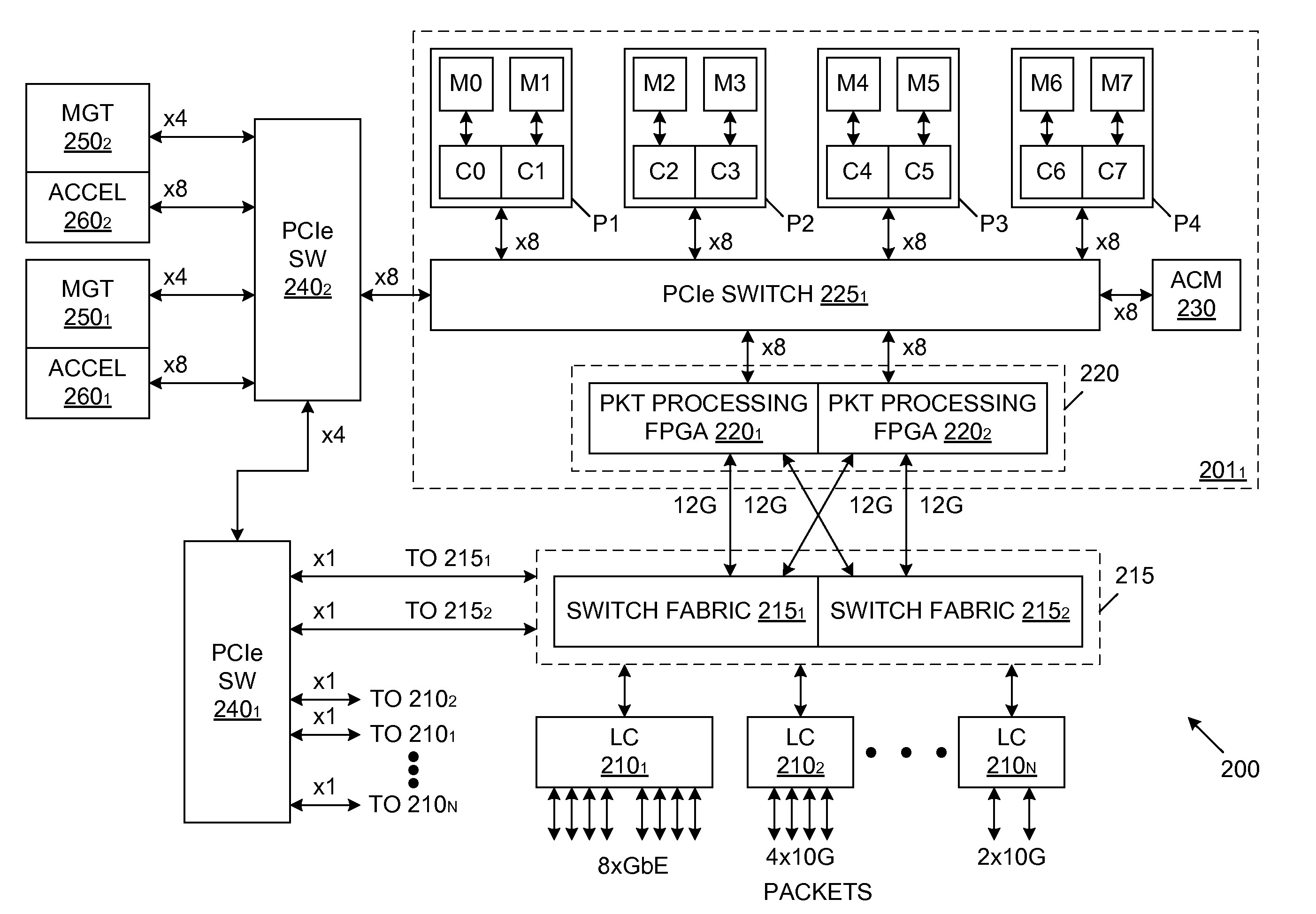
[0017]The present invention provides a unique method to use PCIe as a fabric in the application layer of a multi-processor network device. More specifically, the present invention uses PCIe switches (and PCIe lanes) to cluster a large number of multi-core processors to increase processing performance.

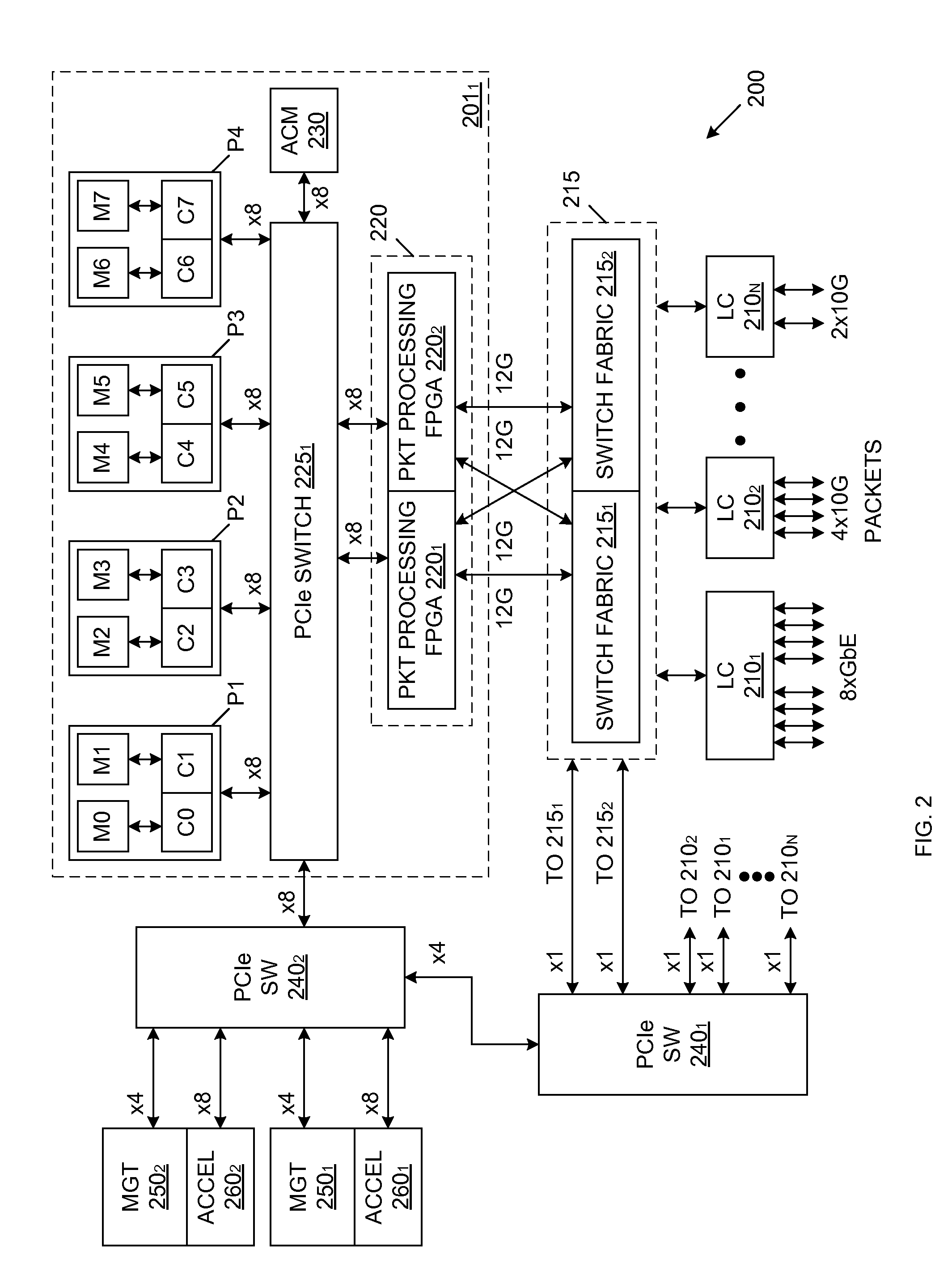
[0018]FIG. 2 is a block diagram of a multi-core network device 200 in accordance with one embodiment of the present invention. Multi-c...


PUM


Abstract

A multi-processor architecture for a network device that includes a plurality of barrel cards, each including: a plurality of processors, a PCIe switch coupled to each of the plurality of processors, and packet processing logic coupled to the PCIe switch. The PCIe switch on each barrel card provides high speed flexible data paths for the transmission of incoming/outgoing packets to/from the processors on the barrel card. An external PCIe switch is commonly coupled to the PCIe switches on the barrel cards, as well as to a management processor, thereby providing high speed connections between processors on separate barrel cards, and between the management processor and the processors on the barrel cards.

Description

FIELD OF THE INVENTION[0001]The present invention relates to multi-processor network devices.RELATED ART[0002]The increase in Internet traffic, particularly streaming media, has created a need for much higher performance networking products in the data center. However, it is also necessary to limit the power requirements of this same data center. This creates a need for a new architecture for network switching devices.[0003]A common approach for achieving higher performance in network switching devices is to increase the operating frequency of the microprocessors used in the network switching device. While increasing the operating frequency has been the preferred method to gain higher performance, this technique is no longer viable. This is partly due to limitations in the power budgets of the network switching devices, as well as limitations in the power allowed in the data center environments where such network switching devices are commonly used.[0004]The semiconductor industry h...

Claims


Application Information

Patent Timeline
IPC IPC(8): G06F13/20G06F13/36
CPCG06F13/4022Y02B60/1235Y02B60/1228G06F2213/0026Y02D10/00
Inventor HAMADANI, MEHRDADBANSAL, DEEPAKMOY, SAM HTINMALLI, SREENIVASULUCHEUNG, DAVIDKANCHERLA, MANIDEVARAPALLI, SRIDHAR
Owner AVAGO TECH INT SALES PTE LTD
Why Eureka
Try Eureka