Method for depositing a fluorinated layer from a precursor monomer

a precursor monomer and fluorinated layer technology, applied in the direction of metal material coating process, plasma technique, coating, etc., can solve the problems of reducing the hydrophobicity of the surface, requiring the use of extremely reactive gases, and requiring the use of sufficiently reactive compounds, so as to reduce the pressure, facilitate handling, and reduce the effect of toxicological and environmental controversy

Inactive Publication Date: 2011-01-20
UNIV LIBRE DE BRUXELIES
View PDF9 Cites 2 Cited by
  • Summary
  • Abstract
  • Description
  • Claims
  • Application Information

AI Technical Summary

Benefits of technology

[0007]The object of the present invention is to propose a method for depositing a fluorinated layer from a precursor monomer which avoids the drawbacks of existing methods. In particular, it attempts to avoid the req

Problems solved by technology

The main limitation in these techniques lies in the fact that they imperatively take place at low pressure (under vacuum).
The major drawback of this type of method is that it requires the use of sufficiently reactive compounds.
Most of these reactive compounds then have the drawback either of directly bearing hydrophilic polar groups, or of reacting in the long term with atmosph

Method used


Image

  • Method for depositing a fluorinated layer from a precursor monomer
  • Method for depositing a fluorinated layer from a precursor monomer
  • Method for depositing a fluorinated layer from a precursor monomer

Examples


example 1

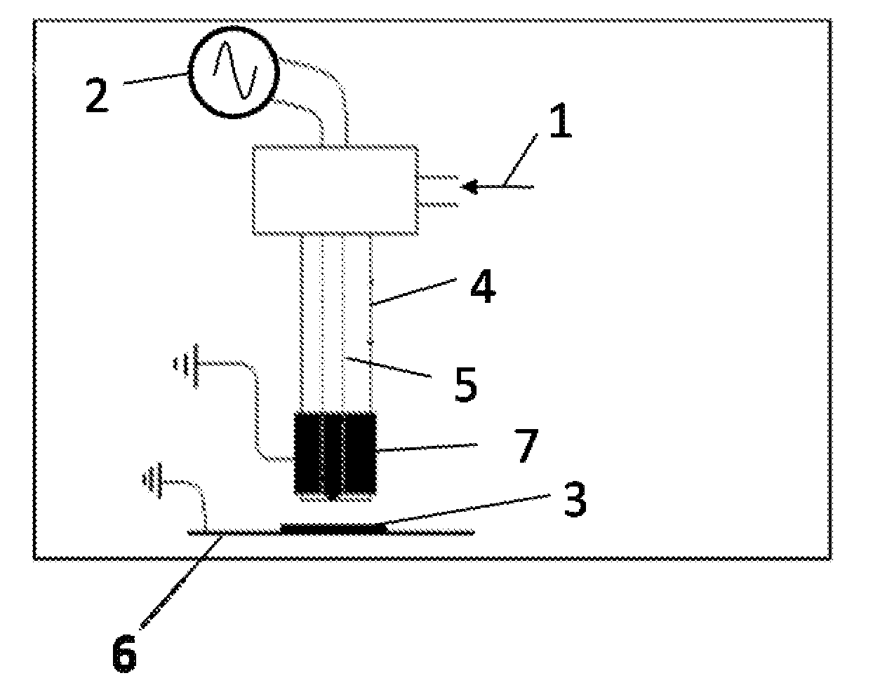
[0050]Example 1 shows a deposit of perfluorohexane on PVC, achieved in post-discharge under the following conditions:

[0051]A sample 3, as a PVC film of 4 cm×4 cm of the Solvay brand is cut out, cleaned with methanol and isooctane and placed at the outlet (at 0.05 cm) of a cold plasma torch (FIG. 1) (discharge with a dielectric barrier) operating at atmospheric pressure. The fluorinated monomer (perfluorohexane) is placed in a glass (Pyrex) bubbler immersed in a Dewar vessel containing a mixture of acetone and dry ice. The temperature of the mixture, and therefore of the monomer, is about −80° C. The vapor pressure of perfluorohexane at this temperature is about 1.2 mbars. An argon flow is then sent into the bubbler, with an initial overpressure of 1.375 bars. The argon / perfluorohexane gas mixture 1 is carried away into the inside of the torch. A plasma is initiated with a voltage of 3,200 Volts and a frequency of 16 kHz for 1 minute.

example 2

[0052]Example 2 shows a deposit of perfluorohexane on PVC produced in a discharge with a dielectric barrier under the following conditions.

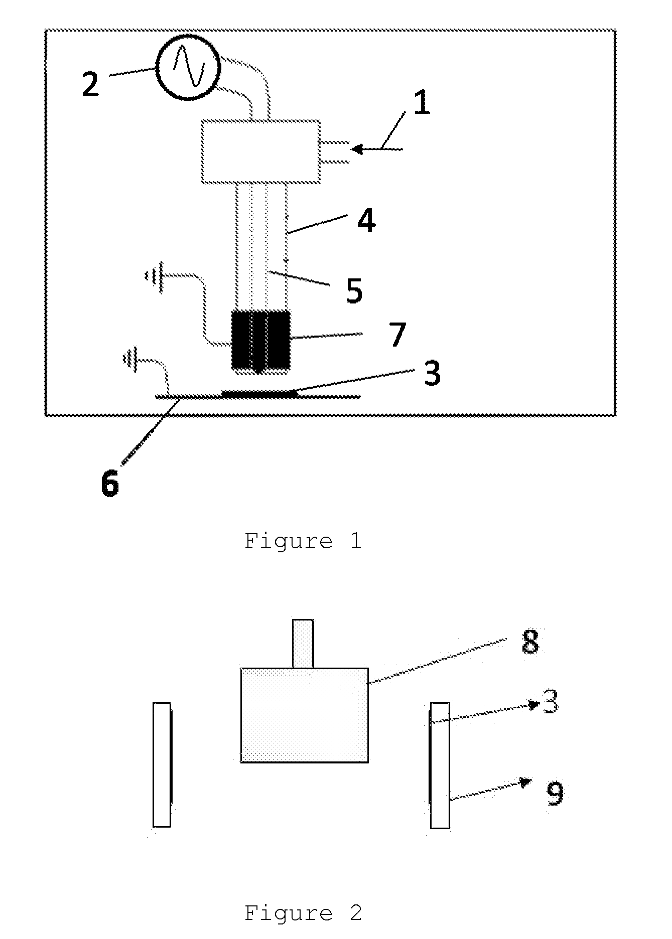
[0053]The sample is attached onto the inside of the external electrode 9 of a discharge with a cylindrical dielectric barrier. The > electrode 8, the one to which the voltage is applied, is the internal electrode covered with an alumina cup. Alumina cement provides the seal (FIG. 2).

[0054]The fluorinated monomer is brought into the discharge as in Example 1. A treatment of 1 minute at a voltage of 3,000 V and a frequency of 20 kHz is applied subsequently (treatment in the discharge area).

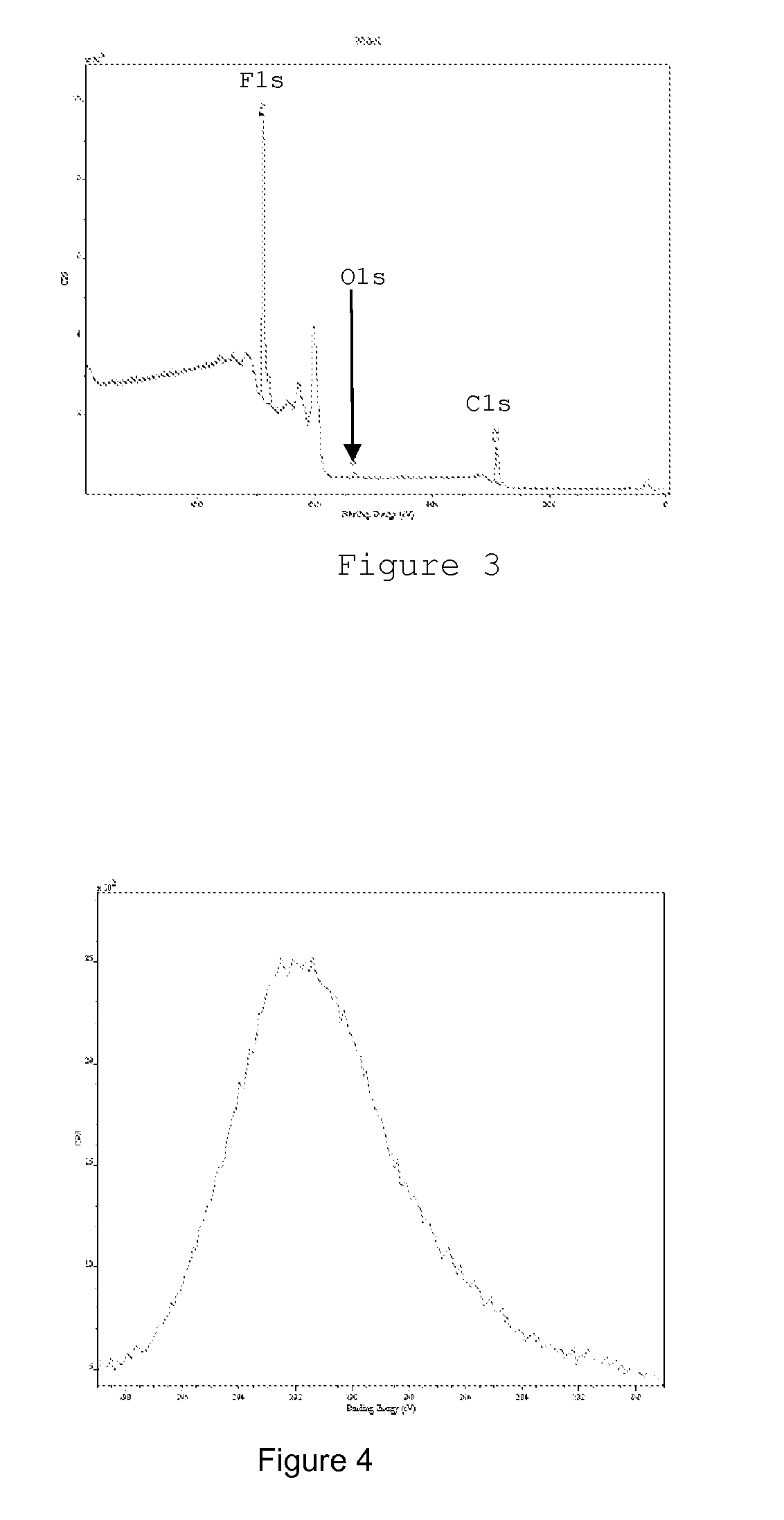
[0055]The unambiguous presence of a fluorinated layer at the surface of the PVC film is proved by X photoelectron spectroscopy. The spectra of FIGS. 3 and 4 illustrate full survey and magnification of the carbon area. The presence of fluorine of CF2 groups is clearly identified via the fluorine peak located at 689 eV and the position of the carbon peak, 291.5 eV ...

example 3

[0057]Example 3 is identical with Example 1, except for the substrate, which in this example is polyethylene.


PUM

PropertyMeasurementUnit
Temperatureaaaaaaaaaa
Pressureaaaaaaaaaa
Pressureaaaaaaaaaa

Abstract

A method for depositing a fluorinated layer on a substrate includes the injection of a gas mixture including a fluorinated compound and a carrier gas in a discharge or post-discharge area of a cold atmospheric plasma at a pressure comprised between 0.8 and 1.2 bars. The fluorinated compound has a boiling temperature at a pressure of 1 bar above 25° C.

Description

FIELD OF THE INVENTION[0001]The invention relates to the deposition of thin layers of hydrophobic compounds at the surface of a substrate.STATE OF THE ART[0002]Modifications of surfaces in order to impart new properties to them are customary things. In this approach, in order to make anti-adhesive surfaces (including towards proteins) dirt-repellent or further (ultra)hydrophobic, it is common to deposit at the surface of the latter a layer, totally or partly consisting of fluorinated molecules.[0003]These methods are presently mainly achieved by the PACVD (plasma assisted chemical vapor deposition) or PECVD (plasma enhanced chemical vapor deposition) technique. The usual technique consists of injecting into a plasma reactor, operating at low pressure, a fluorinated gas monomer (CF4 being the simplest, but many alternatives exist, such as C2F6, C3F8, C4F8, fluoroalkylsilanes, eta . . . ).[0004]The type of plasma used (RF, microwave plasma, . . . ) differs depending on the studies, bu...

Claims


Application Information

Patent Timeline
IPC IPC(8): C23C16/00
CPCB05D5/083B05D1/62
Inventor RENIERS, FRANCOISVANDENCASTEELE, NICOLASBURY, OLIVIER
Owner UNIV LIBRE DE BRUXELIES
Why Eureka
Try Eureka