
Plasma treatment apparatus and method for treatment of a substrate with atmospheric pressure glow discharge electrode configuration

a technology of plasma treatment apparatus and substrate, which is applied in the direction of instruments, record information storage, transportation and packaging, etc., can solve the problems of inferior barrier properties, inflexibility and fragility, and weight of plasma, and achieve the effect of improving plasma stability

Inactive Publication Date: 2011-01-20
FUJIFILM MFG EURO
View PDF8 Cites 20 Cited by
  • Summary
  • Abstract
  • Description
  • Claims
  • Application Information

AI Technical Summary

Benefits of technology

[0012]The present invention seeks to provide a plasma treatment apparatus and a method for treating a substrate, such as depositing one or more layers of inorganic barrier material on a polymeric substrate, using an atmospheric pressure glow discharge plasma, which has an improved plasma stability.
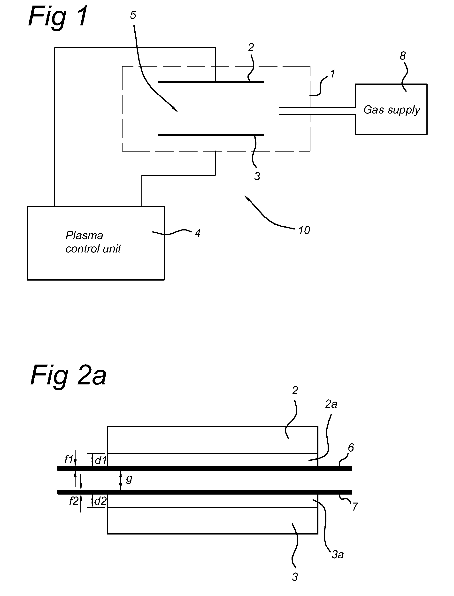
[0016]The plasma treatment apparatus according to the present invention provides an improved plasma stability, resulting from a lower voltage drop across the dielectric barrier of the DBD electrode structure. Furthermore, the DBD electrode structure is easier and more cost-effective to produce. By controlling the product of gap distance and total dielectric distance actively to a value less than 1, 0.5, 0.2 or even 0.1 mm2, and making an adaptation of the gap distance dependent on the actual total dielectric distance (which may vary depending on the type of substrate being processed), the improved stability is obtained.

Problems solved by technology

Main disadvantage of the use of glass is related to its weight, inflexibility and fragility.
Disadvantages of the use of polymeric substrates are their lower chemical resistance and inferior barrier properties.
Another drawback is dust formation upon using an atmospheric glow discharge plasma for deposition purposes.
It is a known fact, that atmospheric pressure glow discharge plasma's used for deposition of a chemical compound or chemical element suffer from dust formation by which formation of a smooth surface cannot be obtained and the used equipment will accumulate the dust in a short period of time resulting in products with worse barrier properties as the roughness of the barrier layer.

Method used


Image

  • Plasma treatment apparatus and method for treatment of a substrate with atmospheric pressure glow discharge electrode configuration
  • Plasma treatment apparatus and method for treatment of a substrate with atmospheric pressure glow discharge electrode configuration
  • Plasma treatment apparatus and method for treatment of a substrate with atmospheric pressure glow discharge electrode configuration

Examples


examples

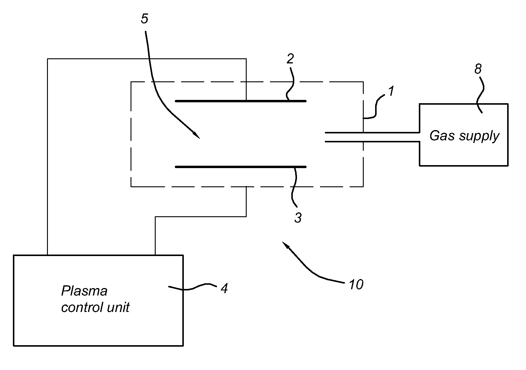
[0078]Several substrates 6, 7 (17.8 cm width and thickness 300, 100 and 50 μm) have been treated using an excitation frequency of 130 kHz and a 500 microseconds pulse on-time with a 80% duty cycle with a heat controlled electrodes 2, 3 at an electrode surface temperature of 70° C. The gas composition in the treatment space 5 comprised a mixture of nitrogen and 5% O2, and HMDSO (600 mg / hr).

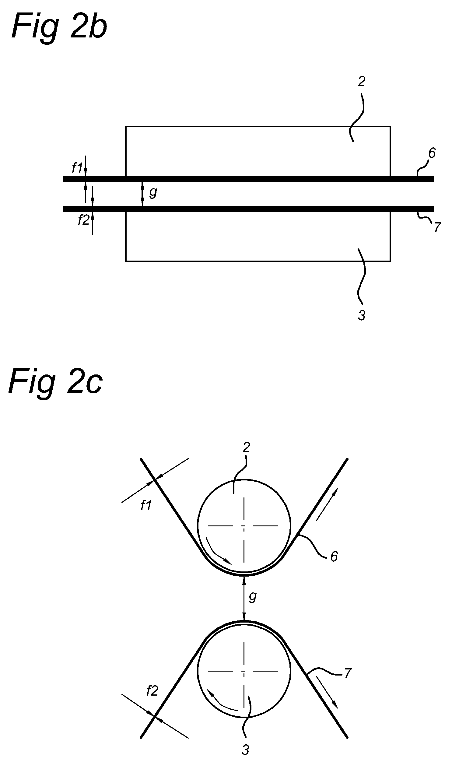
[0079]Roll-electrode 3 (with radius 1.5 meter) and a roll-electrode 2 (with a radius of 5 cm) and flat electrodes 2, 3 were used without and with additional dielectric layer 2a, 3a. The substrates 6 and 7 served in part of the experiments as the dielectric barriers. By using substrates 6 and 7 with and without additional dielectric layers 2a,3a the total dielectric thickness could be varied within the desired range, so the total dielectric thickness d could be varied.

[0080]Table 1 lists a number of comparative examples and inventive examples. The deposited SiO2 barrier amount was varied by adjustin...


PUM

PropertyMeasurementUnit
Fractionaaaaaaaaaa
Areaaaaaaaaaaa
Areaaaaaaaaaaa

Abstract

Plasma treatment apparatus and method for treating a substrate (6, 7) e.g. for deposition of a layer on the substrate (6, 7). Two opposing electrodes (2, 3) and a treatment space (5) are provided. A dielectric barrier (6, 7; 2a, 3a), comprising in operation the substrate, is provided in the treatment space (5) between the at least two opposing electrodes (2, 3) which are connected to a plasma control unit (4). A gap distance (g) is the free distance in the treatment space (5) of a gap between the at least two opposing electrodes (2, 3) in operation. A total dielectric distance (d) is the sum of the dielectric thickness of the dielectric layers (2a, 3a) and the substrate (6, 7). The product of gap distance (g) and total dielectric distance (d) is controlled to a value less than or equal to 1.0 mm2.

Description

FIELD OF THE INVENTION[0001]The present invention relates to a plasma treatment apparatus and a method for treatment of a substrate using an atmospheric pressure glow discharge plasma in a treatment space. Furthermore, the present invention relates to a polymeric substrate suitable for use as a substrate in flexible electronic devices, in particular electroluminescent such as organic light emitting display (OLED) devices.PRIOR ART[0002]European patent application EP-A-1 905 512 discloses a method and apparatus for producing a photo catalytic material using a plasma discharge in an oxygen containing gas atmosphere. The independent claims explicitly mention the use of a dielectric barrier discharge in a specific form, i.e. silent discharge or creeping discharge. Such a type of discharge is different from an atmospheric pressure glow discharge. In essence, a higher energy density is provided in the plasma. In paragraph [0020] it is even explicitly stated that the invention as disclosed...

Claims


Application Information

Patent Timeline
IPC IPC(8): C23C16/00C23C16/44C23C16/513B32B3/00
CPCH01J37/32348H01J37/32825C23C16/402C23C16/515C23C16/545H05H1/2406Y10T428/24355H05H2001/2431H01J37/32018H01J37/32752H01L51/0097H01L51/5253Y02E10/549H05H2001/2412H05H1/2431H10K77/111H10K59/873H10K50/844
Inventor DE VRIES, HINDRIK WILLEM
Owner FUJIFILM MFG EURO
Learn More