Manufacturing method for planar independent-gate or gate-all-around transistors

Active Publication Date: 2011-01-20
UNITED MICROELECTRONICS CORP
View PDF7 Cites 18 Cited by
  • Summary
  • Abstract
  • Description
  • Claims
  • Application Information

AI Technical Summary

Benefits of technology

[0052]the (second) active regions used for the planar bulk FET are provided without a sacrificial layer;
[0053]In one embodiment, step d) of the method of the first aspect of the invention is additionally performed in a manner adapted for the fabrication of a planar bulk FET in the second active semiconductor region.
[0054]Therefore, a co-integration of a planar IDGFET or a planar GAAFET with standard bulk FETs fits well into the basic processing scheme of the present invention.
[0055]It is further possible to combine the fabrication of the IDG

Problems solved by technology

FinFET devices have the disadvantage that they have a higher access resistance and a degraded NMOS mobility for (110) fin surfaces.
Furthermore, problems arise in dopant implantation due t

Method used


Image

  • Manufacturing method for planar independent-gate or gate-all-around transistors
  • Manufacturing method for planar independent-gate or gate-all-around transistors
  • Manufacturing method for planar independent-gate or gate-all-around transistors

Examples


Embodiment Construction

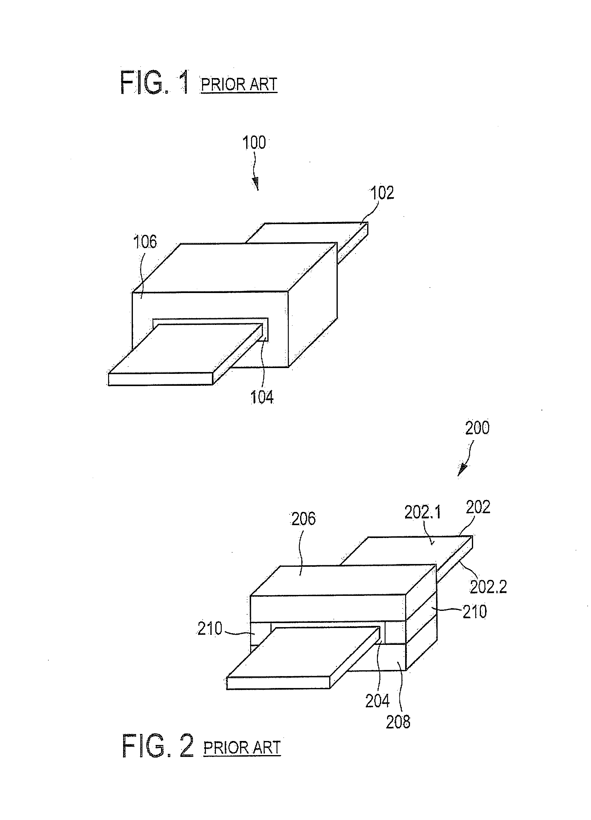
[0060]FIGS. 1 and 2 show schematic three-dimensional illustrations of a planar GAAFET and a planar IDGFET. The structures shown in FIGS. 1 and 2 represent general features of a GAAFET and of a IDGFET, which are as such known in the art.

[0061]The GAAFET 100 of FIG. 1 has a channel layer 102, which extends between a source region (not shown) and a drain region (not shown). The channel layer is surrounded by a dielectric layer 104 and an electrically conductive gate layer 106. The IDGFET 200 of FIG. 2 has a channel layer 202, which extends between a source region (not shown) and a drain region (not shown). The channel layer 202 is surrounded by a dielectric layer 204. Two main surfaces 202.1 and 202.2 of the channel layer face respective gate layers 206 and 208. The sidewalls of the channel face an insulating layer 210.

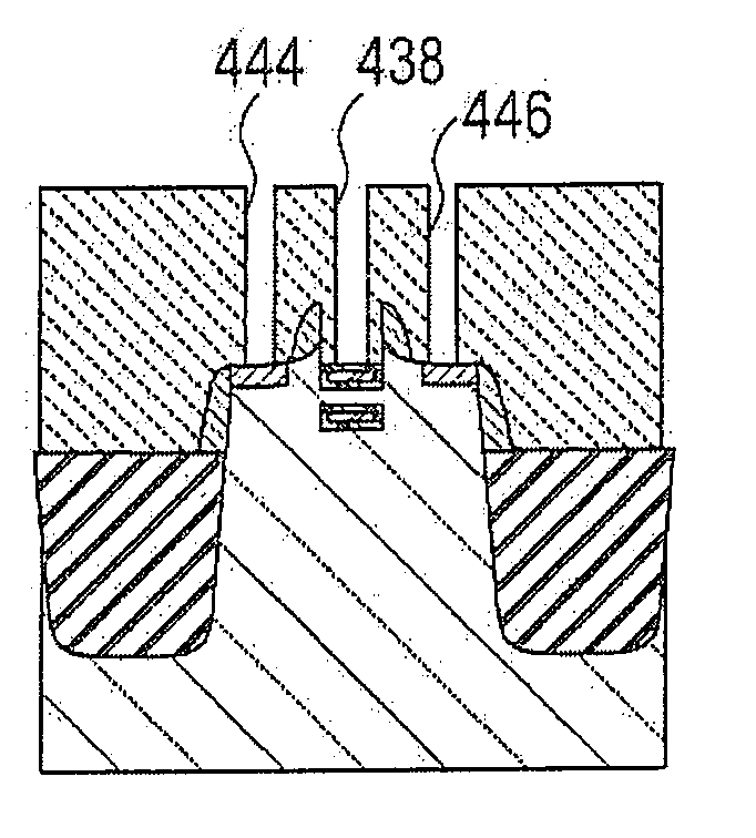
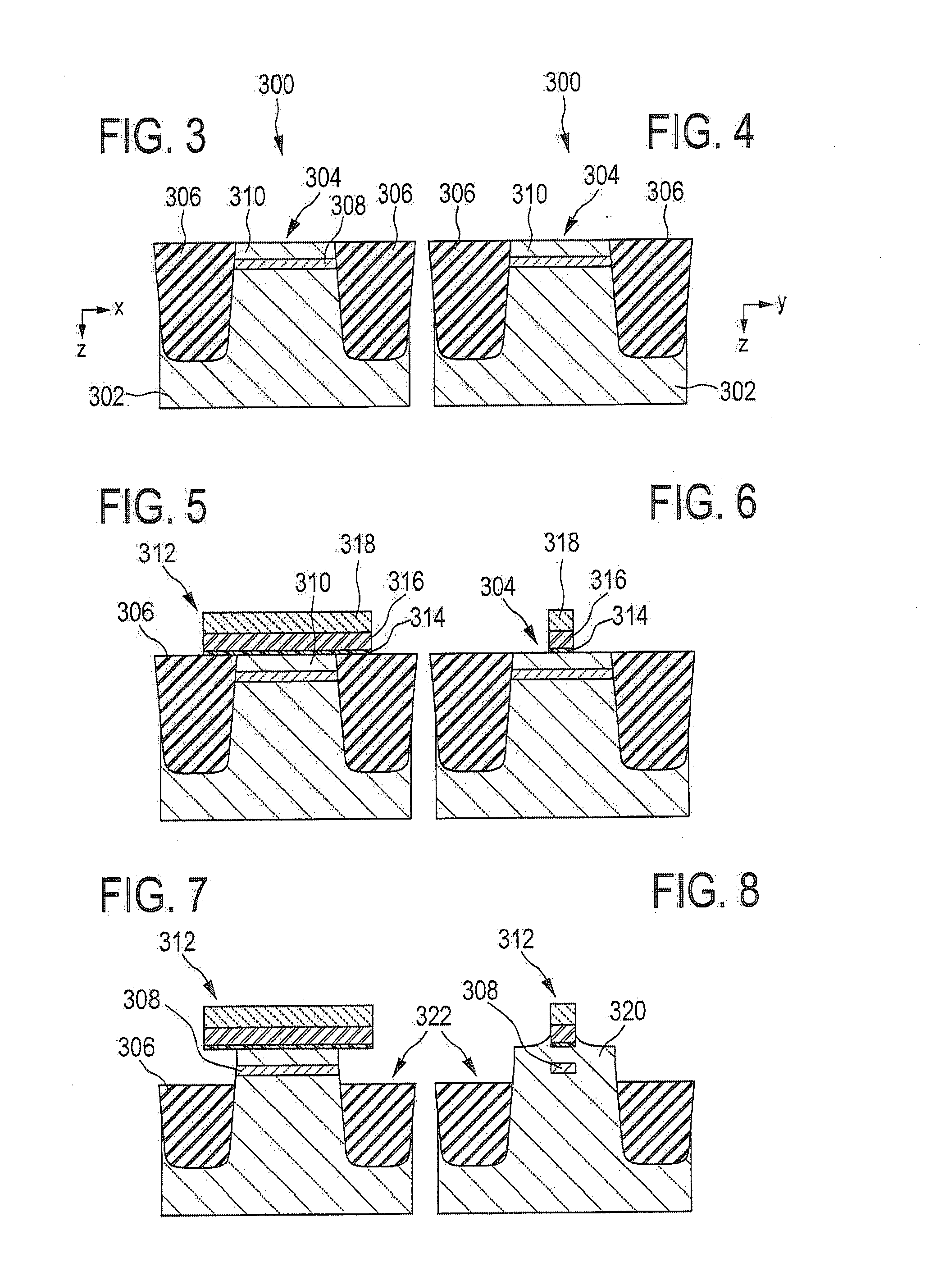
[0062]FIGS. 3 to 20 show cross-sectional views of a planar IDGFET during different stages of its fabrication. The Figures are grouped in pairs. Each pair of Figures repr...


PUM


Abstract

The present invention relates to a method for fabricating a planar independent-double-gate FET or a planar gate-all-around FET on a bulk semiconductor substrate. The method comprises refilling a surface recess in an active semiconductor region with a buried sacrificial layer, and, after preparing a pre-processing a gate stack by respective deposition and patterning, the formation of a recess in the isolation regions so as to cause the recess to extend, in a depth direction that points towards the inner substrate, to a depth level that allows removing the buried sacrificial layer and so as to cause the recess to undercut portions of gate stack in the channel direction.

Description

FIELD OF THE INVENTION[0001]The present invention relates to a method for manufacturing a planar independent-gate field effect transistor (IDGFET) and to a method for manufacturing a planar gate-all-around field effect transistor (GAAFET).BACKGROUND OF THE INVENTION[0002]Among the transistor structures favored for use in transistor structures with channel length of 50 nm or less, double gate (DG) or gate-all-around structures are widely considered as the most promising CMOS structures.[0003]Different kinds of such multi-gate structures are envisioned, such as FinFET, vertical structures, or planar structures, according to the orientation of the conduction film and the respective fabrication process.[0004]The planar architecture has the advantage to be able to stack several conduction channels vertically, i.e., to keep the same layout density as a bulk planar architecture, but to accommodate a higher current in comparison with the planar architecture. Inversely, it is also possible t...

Claims


Application Information

Patent Timeline
IPC IPC(8): H01L21/336
CPCH01L29/42392H01L29/66484H01L29/78654H01L29/66772H01L29/7831H01L29/66636
Inventor POUYDEBASQUE, ARNAUDCORONEL, PHILIPPEDENORME, STEPHANNE
Owner UNITED MICROELECTRONICS CORP
Why Eureka
Try Eureka