
Cryptographic communication system and gateway device

a communication system and gateway technology, applied in the field of cryptographic communication systems and gateway units, can solve the problems of low throughput and low performance of the terminal, and achieve the effect of intensively disposing of the communication device and avoiding the influence of performan

Inactive Publication Date: 2011-01-20
HITACHI LTD
View PDF10 Cites 34 Cited by
  • Summary
  • Abstract
  • Description
  • Claims
  • Application Information

AI Technical Summary

Benefits of technology

[0020]A third object of the invention is to make it possible to transfer only the necessary communication to the intensive device depending on the communication conditions when the service provider adds the device via which the terminal gains access to the server on the internet.
[0021]As described above, one of the objects of the invention is to avoid the duplicate encryption process of the terminal. Moreover, one of the objects of the invention is to enable the terminal to use the server on the internet seamlessly while connection to the corporate network is held. Furthermore, one of the objects of the invention is to make it possible to transfer only the necessary communication to the intensive device depending on the communication conditions when the service provider adds the device via which the terminal gains access to the server on the internet.
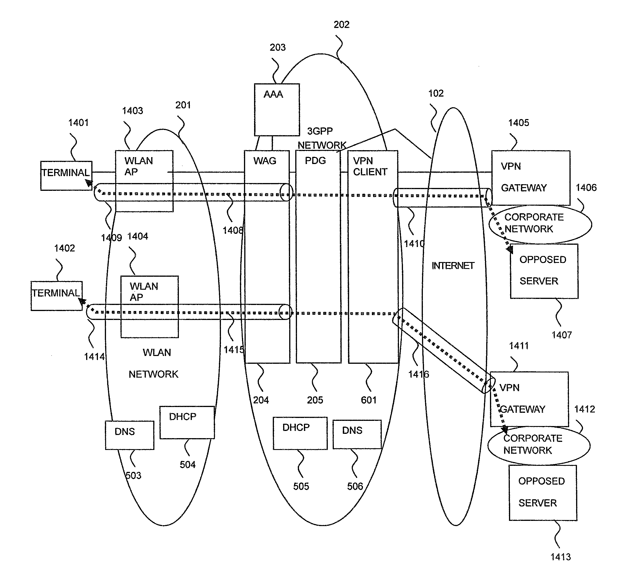
[0024]In this communication system, the PDG comprises a communication block processing section for blocking the communication of the terminal and asking for the authentication when firstly accessed from the terminal, a VLAN setting section for registering the VLAN for the terminal to identify the terminal between the PDG and the VPN client after being notified of authentication success of the terminal from the AAA, a tunnel setting section for setting the first tunnel of the WLAN network between the terminal and the PDG at the request from the terminal, a tunnel setting sending section for sending a request for setting the second tunnel in the corporate network after setting the first tunnel of the WLAN network, a message receiving section for receiving the message via the first tunnel from the terminal, and a message transfer section for transferring the message received via the first tunnel from the terminal to the opposed server via the second tunnel, and can solve one of the above-mentioned problems on the performance and power consumption through a dual encryption process of the terminal.
[0025]Also, in this communication system, the PDG comprises an IP address translation table storing the information for translating the source IP address of the message to the corporate network or global IP address, an address translation section for searching the IP address translation table, based on the destination IP address of the message or the source IP address of the message, and translating the source address of the message to the corporate network or global IP address, based on the search result, and a message transfer section for transferring the message in which the source IP address is translated to the IP address of the corporate network to the corporate network via the second tunnel of the corporate network, or the message in which the source address is translated to the IP address of the internet network to the internet, and can solve one of the above-mentioned problems that the terminal can not use the server on the internet seamlessly while holding the connection to the corporate network.
[0041]According to the invention, when the terminal using the internet access via the WLAN network provided by the 3GPP network uses the remote VPN of the corporate network, it is possible to avoid the influence on the performance due to the dual processing of the IPSec. Also, according to the invention, when the terminal using the internet connection service via the 3GPP network uses the remote VPN of the corporate network, it is possible to utilize the service on the internet seamlessly while connection to the corporate network is held. Further, according to the invention, in adding the communication device via which the terminal is interconnected, it is possible to intensively dispose the communication device without need of installing the communication device in each zone.

Problems solved by technology

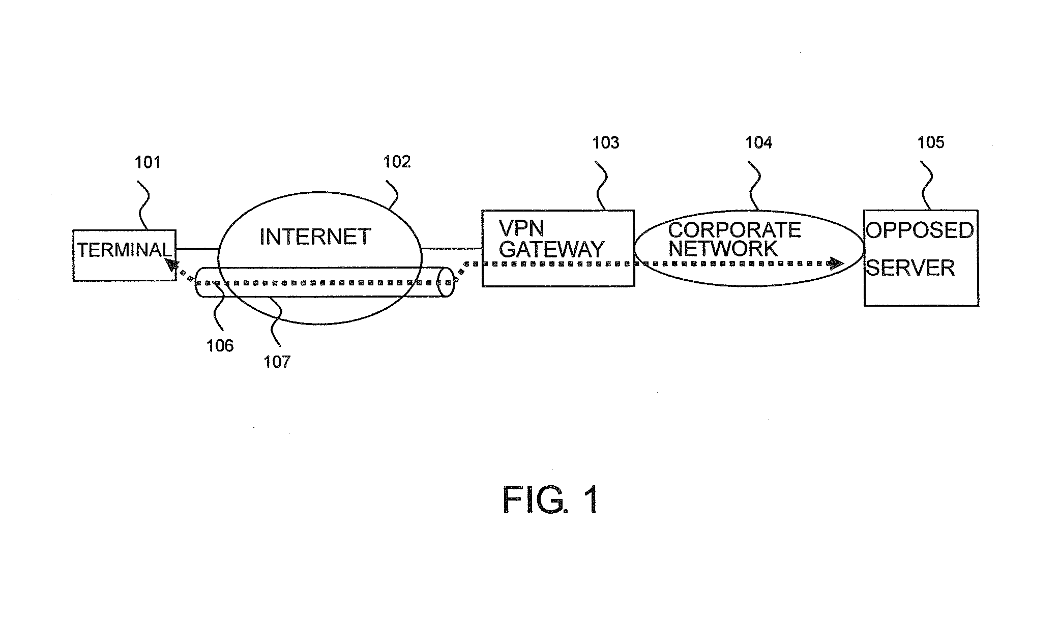
In the terminal 101, a dual IPSec process consumes more CPU resources of the terminal, resulting in a problem on the performance and consumption power at the terminal having low throughput.

Method used


Image

  • Cryptographic communication system and gateway device
  • Cryptographic communication system and gateway device
  • Cryptographic communication system and gateway device

Examples


Embodiment Construction

[0061]An embodiment of the invention will be described below in detail with reference to the drawings. The same or like parts are designated by the same reference numerals and not described repeatedly.

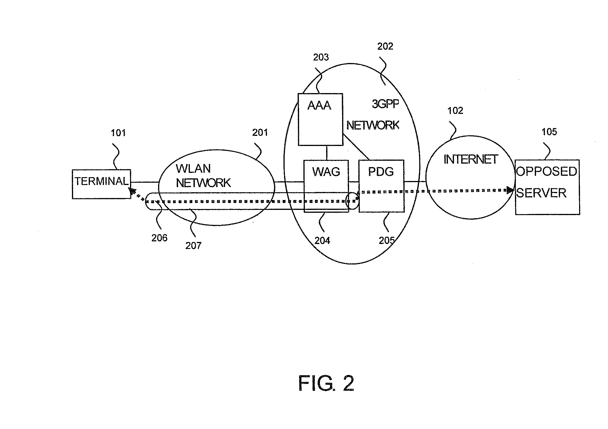
[0062]Referring to FIG. 6, the remoter access to a corporate network using an internet connection service of a 3GPP network according to this embodiment will be described below. In FIG. 6, the network comprises a WLAN network (first network) 201, a 3GPP network 202, the internet (second network) 102, and a corporate network (third network) 104. The 3GPP network 202 comprises a WAG 204, a PDG (gateway unit) 205, an AAA (authentication device) 203, a VPN client 601, a DHCP 505, and a DNS 506. The corporate network 104 comprises a VPN gateway 103 and an opposed server 105. The WLAN network 201 connects a terminal 101 via a WLAN Access Point (WLAN AP) to the 3GPP network 202. The internet 102 connects the 3GPP network 202 and the corporate network 104.

[0063]Through a communication link 206...


PUM


Abstract

A GW (PDG) at the termination of remote access is installed in the 3GPP system. After an IPSec tunnel between a terminal and the GW is opened, an IPSec tunnel between a VPN client and the corporate network GW is opened, whereby the data from the terminal is transferred via two tunnels between the terminal and the GW and between the VPN client and the corporate network GW to the corporate network. Also, the GW checks if the destination network uses the global address from the destination IP address of a message received from the terminal making the remote VPN access. If the global address is required, the source IP address of the message received from the terminal is translated from the private address for use within the corporate network to which the terminal is allocated to the global address to transfer the message.

Description

BACKGROUND OF THE INVENTION[0001]1. Field of the Invention[0002]The present invention relates to a cryptographic communication system and a gateway unit, and more particularly to a cryptographic communication system and a gateway unit for providing a remote VPN access service to a corporate network via a 3GPP system having an IP address translation function.[0003]2. Description of the Related Art[0004]With a Virtual Private Network (VPN) technique using a Security Architecture for the Internet Protocol (IPSec), a remote VPN access has widespread for allowing a member going out to make secure connection via the internet to the company's corporate network.[0005]Referring to FIG. 1, the outline of a remote VPN access system will be described below. In FIG. 1, a terminal 101 is connected via the internet 102 to a corporate network 104. The terminal 101 communicates with an opposed server 105 of the corporate network 104 through a communication link 106, but since the communication link ...

Claims


Application Information

Patent Timeline
IPC IPC(8): H04L9/00H04L12/66H04L12/70H04W8/26H04W12/06H04W88/16
CPCH04L12/4633H04L12/4641H04L29/12367H04L61/2514H04W12/04H04L63/061H04L63/164H04W12/02H04L63/0272H04W12/03
Inventor MOTOYAMA, SHINYASHIMIZU, SATOSHINOBE, TADASHIWAKAI, JUNNOSUKE
Owner HITACHI LTD
Learn More