Plasma generating apparatus

Inactive Publication Date: 2011-01-27
DELTA ELECTRONICS INC
View PDF8 Cites 18 Cited by
  • Summary
  • Abstract
  • Description
  • Claims
  • Application Information

AI Technical Summary

Benefits of technology

[0009]The present invention utilizes the slow wave antenna to transmit microwave so that the energy of the microwave can be axially transmitted along the dielectric tube with nearly no attenuation and can induce surface wave. The phase velocity of the surface wave is slower than light speed, thus the surface wave is slow wave which can transmit with nearly no attenuation and then can radically couple to the plasma area

Problems solved by technology

However, once the electromagnetic wave is radiated from a certain area of the conductive antenna, the microwave energy in the certain area will consequently decrease.
Therefore, the farther the electrom

Method used


Image

  • Plasma generating apparatus
  • Plasma generating apparatus
  • Plasma generating apparatus

Examples


Embodiment Construction

[0025]A detailed description of the present invention will be made with reference to the accompanying drawings.

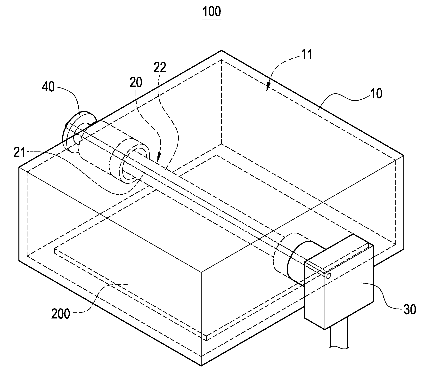
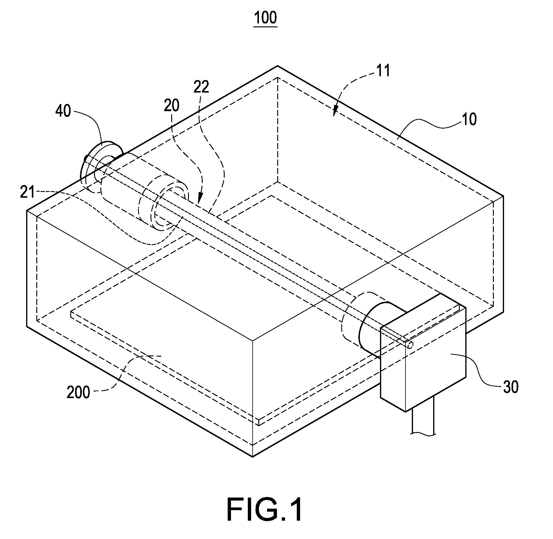
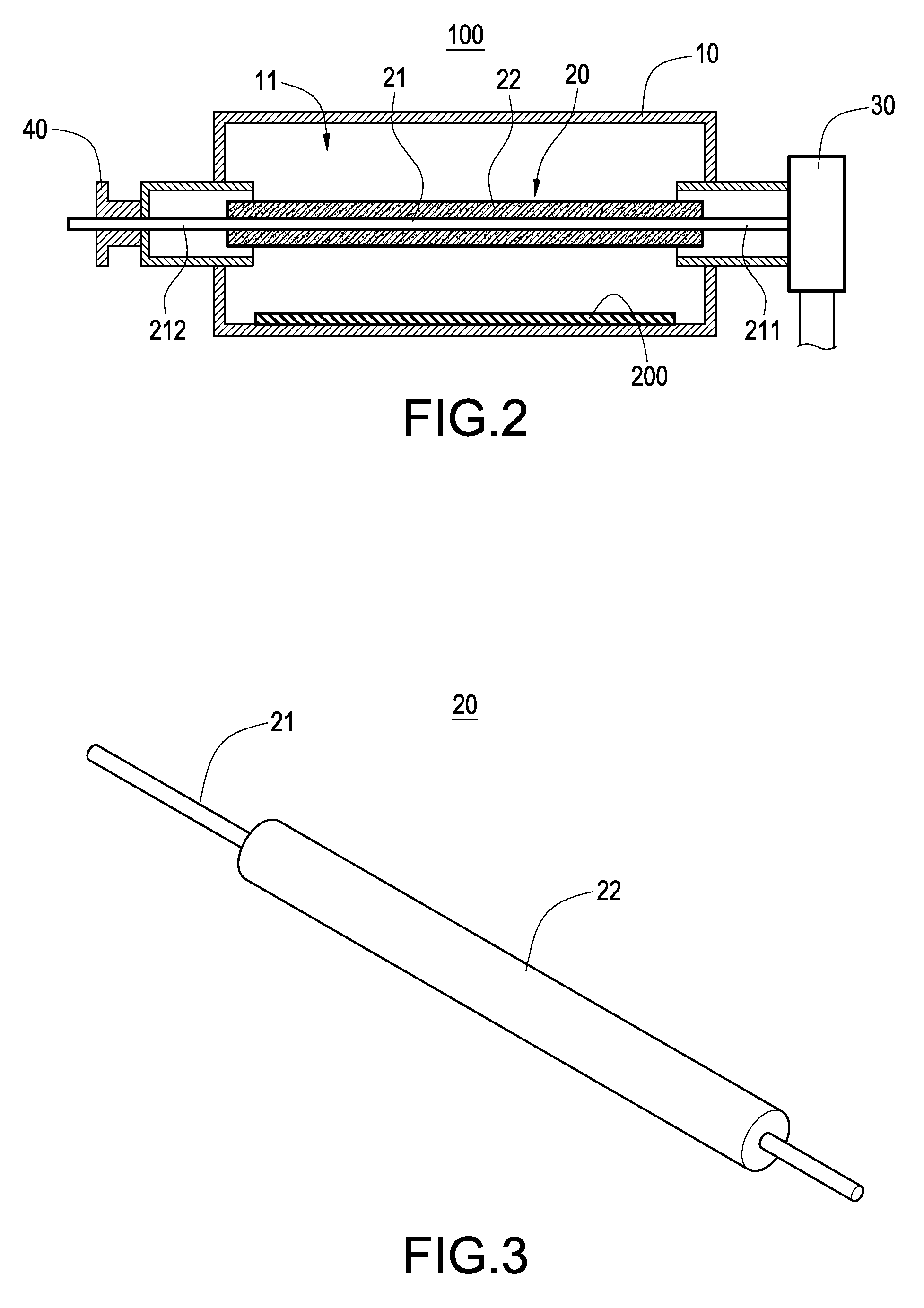
[0026]FIG. 1 and FIG. 2 show a plasma generating apparatus according to a first embodiment of the present invention. The plasma generating apparatus 100 is used for performing thin film depositing process or thin film etching process for a substrate. The plasma generating apparatus 100 mainly includes a chamber 10, a slow wave antenna 20, and an electromagnetic wave generator 30.

[0027]The chamber 10 is of rectangular shaped. The chamber 10 can be made of metal material, but not limited thereto. The chamber 10 has an accommodating space 11 for arranging a substrate 200.

[0028]The slow wave antenna 20 is substantially arranged in the accommodating space 11. The slow wave antenna 20 has a central conductive tube 21 passing through the accommodating space 11, and a dielectric tube 22 arranged around the central tube 21. The dielectric tube 22 is tightly fit around the central tu...


PUM


Abstract

A plasma generating apparatus includes a chamber, a slow wave antenna and an electromagnetic wave generator. The chamber has an accommodating space. The slow wave antenna has a central conductive tube passing through the accommodating space, and a dielectric tube arranged around the central tube. The electromagnetic wave generator is used for coupling electromagnetic wave into the slow wave antenna. An electromagnetic wave transmitted by the electromagnetic wave generator can pass through the slow wave antenna and radiate into the accommodating space.

Description

BACKGROUND OF THE INVENTION[0001]1. Field of the Invention[0002]The present invention relates to a plasma generating apparatus, in particular to a plasma generating apparatus used for thin film depositing process or thin film etching process.[0003]2. Description of Related Art[0004]Plasma enhanced chemical vapor deposition (PECVD) is a kind of technique of forming a thin film. Generally speaking, PECVD technique can be divided into two main catalogs including radio frequency (RF) stimulated plasma and microwave stimulated plasma. RF plasma apparatus can be further divided into two catalogs including capacitively coupled plasma (CCP) and inductively coupled plasma (ICP). Microwave plasma apparatus was get more and more attention, for having advantages such as higher plasma density, higher electron ionization coefficient, having no electrode and simpler structure.[0005]In order to get larger processing area, microwave plasma generating device can be designed into linear shape, which h...

Claims


Application Information

Patent Timeline
IPC IPC(8): H05H1/24
CPCH05H1/24H05H1/46H05H1/463
Inventor KOU, CHWUNG-SHANPAN, YAN-RULIN, SHIN-HUAWANG, TENG-WEICHAN, YI-HSIANGLIN, JUI-YU
Owner DELTA ELECTRONICS INC
Why Eureka
Try Eureka