Electric circuit for converting direct current into alternating current

a technology of alternating current and electric circuit, which is applied in the field of electric power generation, can solve the problems of transformer loss, increased cost of conversion stage, and increased cost of photovoltaic facilities as a whole, and achieves the effect of high yield

Inactive Publication Date: 2011-01-27
INGETEAM POWER TECH
View PDF7 Cites 23 Cited by
  • Summary
  • Abstract
  • Description
  • Claims
  • Application Information

AI Technical Summary

Benefits of technology

[0001]The invention, as stated in the heading of this description, relates to an electrical circuit for converting direct current electric power into alternating current electric power. The main field of application of the invention is the industry for the design of electronic devices, and more specifically the sector that designs power systems for the conversion of photovoltaic solar power. The invention can also be applied to other fields such as that of power generation using electro-chemical

Problems solved by technology

However, the output transformer has several disadvantages: since it operates at a low frequency, the transformer is very large and heavy, thereby significantly increasing the cost of the conversion stage, and therefore making the photovoltaic facility more expensive as a whole.
Also, the transformer produces losses that reduce the converter's performance.
However, the galvanic insulation between the photovoltaic system and the grid is lost, deteriorating the system's performance in terms of EMC.
This “non-injection” can be achieved by means of a precise yet expensive and complex control existing in the current state of the technique.
The use of unipolar PWM gives poor performance from the EMC point of view, meaning that its use is not recommended in transformerless systems.
However, bipolar modulation presents two disadvantages in relation to unipolar modulation.
However, as in the case of the H bridge, given that it is a reducing structure, it requires an input voltage higher than the maximum grid voltage, which limits the inp

Method used


Image

  • Electric circuit for converting direct current into alternating current
  • Electric circuit for converting direct current into alternating current
  • Electric circuit for converting direct current into alternating current

Examples


first embodiment

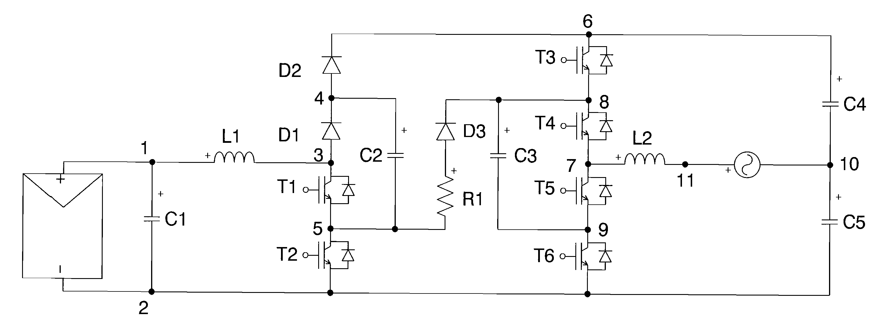
[0053]FIG. 7. Provides a circuit diagram of an electrical circuit for converting direct current electric power into alternating current electric power in photovoltaic systems, according to the invention.

[0054]FIG. 8. Is the circuit of the preceding FIG. 7 showing a definition of the variables mentioned in the following section of this description.

[0055]FIG. 9. Is the circuit of the previous FIG. 7 showing the circulation of current in a first functioning mode.

[0056]FIGS. 10a, 10b, 10c and 10d. Represent the circuit of the previous FIG. 7 showing the circulation of current in a second functioning mode.

[0057]FIG. 11. Is the circuit of the previous FIG. 7 showing the circulation of current in a third functioning mode.

second embodiment

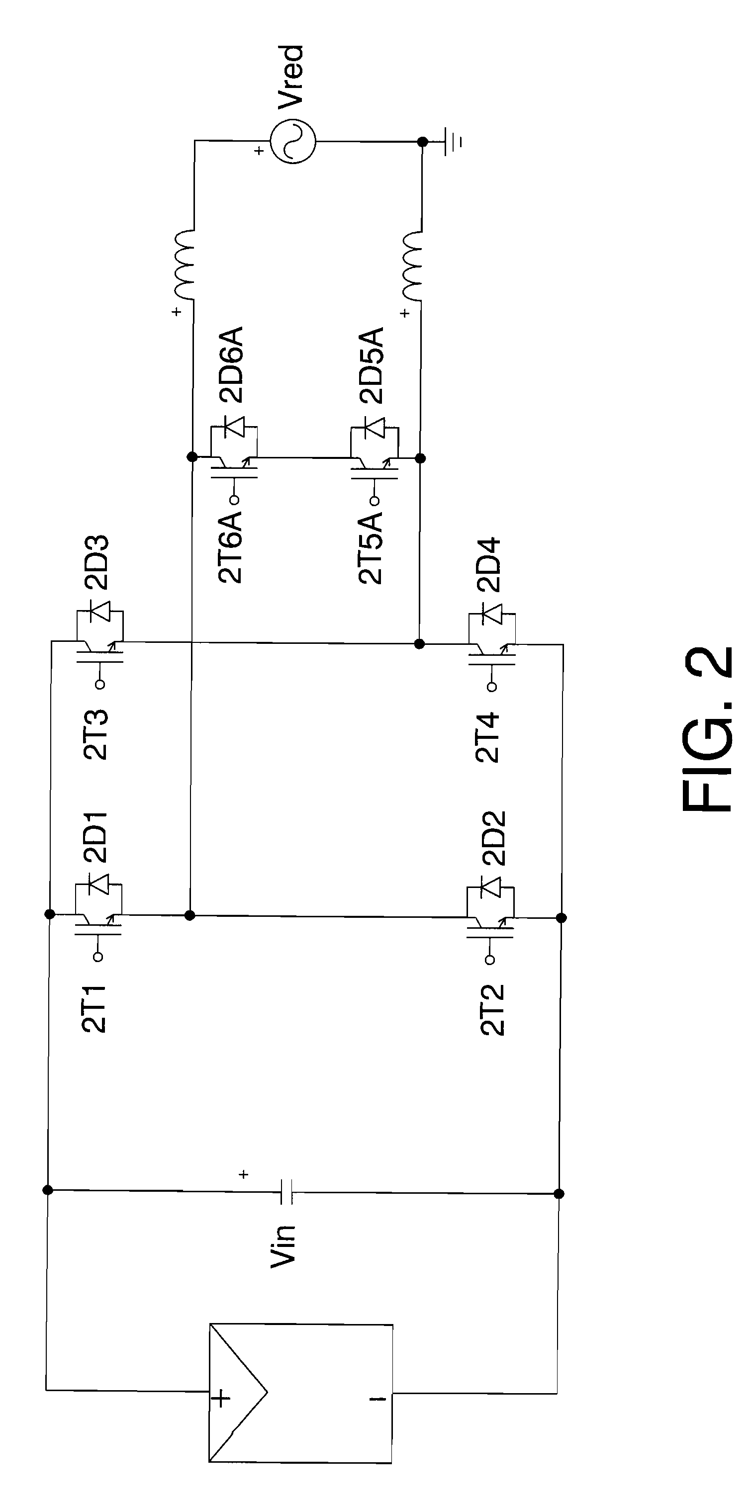
[0058]FIG. 12. Represents the circuit diagram of an electrical circuit for converting direct current electric power into alternating current electric power in photovoltaic systems according to the invention.

DESCRIPTION OF ONE OR SEVERAL MODES OF EMBODIMENT OF THE INVENTION

[0059]What follows is a description of two examples of the invention quoting references from the drawings.

[0060]Thus, the first embodiment of the circuit of the invention appears in FIGS. 7 to 11.

[0061]As can be appreciated from FIG. 7 the circuit of this first embodiment comprises:[0062]Two direct current connections, points 1 and 2, to which the corresponding source of direct current is connected;[0063]A first temporary power accumulator C1 connected between points 1 and 2;[0064]A first branch with at least one first inductance L1 connected between points 1 and 3 of FIG. 7;[0065]A second branch consisting of two switching elements in series, T1 and T2, connected between points 3 and 2 shown in said FIG. 7;[0066]A...


PUM


Abstract

The invention relates to a DC/AC conversion structure, preferably intended for photovoltaic systems, having a high yield across the entire input voltage range thereof, thereby guaranteeing that direct current is not injected into the alternating current network. In a preferred embodiment, the circuit includes six switching elements (T1 to T6) controlled by a command unit. In addition, the circuit includes a capacitive divider (C4 and C5) having the negative of the photovoltaic field connected to one of the ends thereof and a network terminal connected at the mid-point of same, which minimises problems of electromagnetic compatibility.

Description

OBJECT OF THE INVENTION[0001]The invention, as stated in the heading of this description, relates to an electrical circuit for converting direct current electric power into alternating current electric power. The main field of application of the invention is the industry for the design of electronic devices, and more specifically the sector that designs power systems for the conversion of photovoltaic solar power. The invention can also be applied to other fields such as that of power generation using electro-chemical cells or other devices that provide direct current. The main object of the invention is to provide a DC / AC (direct current / alternating current) conversion structure especially designed for photovoltaic systems connected to the power grid, preferably transformerless, which manages to function with a wide range of input voltages, has a high yield across the entire voltage range and does not inject direct current into the grid; additionally minimising problems of electrom...

Claims


Application Information

Patent Timeline
IPC IPC(8): H02M7/537
CPCH02J3/383Y02E10/563H02M7/487H02M7/48H02J2300/24H02J3/381Y02E10/56H02M7/4837
Inventor GONZALEZ SENOSIAIN, ROBERTOCOLOMA CALAHORRA, JAVIERMARROYO PALOMO, LUIS
Owner INGETEAM POWER TECH
Why Eureka
Try Eureka