
Process of closing an opening in a component

Inactive Publication Date: 2011-02-03
GENERAL ELECTRIC CO
View PDF43 Cites 7 Cited by
  • Summary
  • Abstract
  • Description
  • Claims
  • Application Information

AI Technical Summary

Benefits of technology

[0009]A feature of the invention is that a component formed of a superalloy that is otherwise difficult to weld is rendered weldable, and openings in the surface of the component can be closed by welding to potentially yield essentially crack-free weld joints.

Problems solved by technology

For this reason, airfoils of gas turbine buckets and nozzles often require complex cooling schemes in which air is forced through internal cooling passages within the airfoil and then discharged through cooling holes at the airfoil surface.
During the casting process, shifting of the cores is prevented by supporting the cores within the mold using quartz rods or similar means, which often result in openings (through-holes) in the casting in the region of the bucket tip.
In some cases, welding is not practical for closing or filling holes due to costs, poor fusion weldability of the material, or restrictions arising from the configuration of the component.
Furthermore, welding techniques involve application of localized heat energy that produces a fusion zone and a base metal heat-affected zone (HAZ) that are prone to liquation and strain age cracking.
Buckets produced from these alloys have been found to be particularly prone to cracking due to their chemical compositions, and particularly their high volume fraction of gamma prime attributable to the combined amounts of titanium and aluminum in these alloys (greater than five weight percent Ti+Al).
The weld and surrounding area are thus incapable of accommodating the strains required to relieve the residual stresses, with the result that the weld and / or heat-affected zone may crack.
Furthermore, prior welding techniques using weldable superalloys such as GTD-222® have not entirely avoided the occurrence of strain age cracking.

Method used


Image

  • Process of closing an opening in a component
  • Process of closing an opening in a component
  • Process of closing an opening in a component

Examples


Embodiment Construction

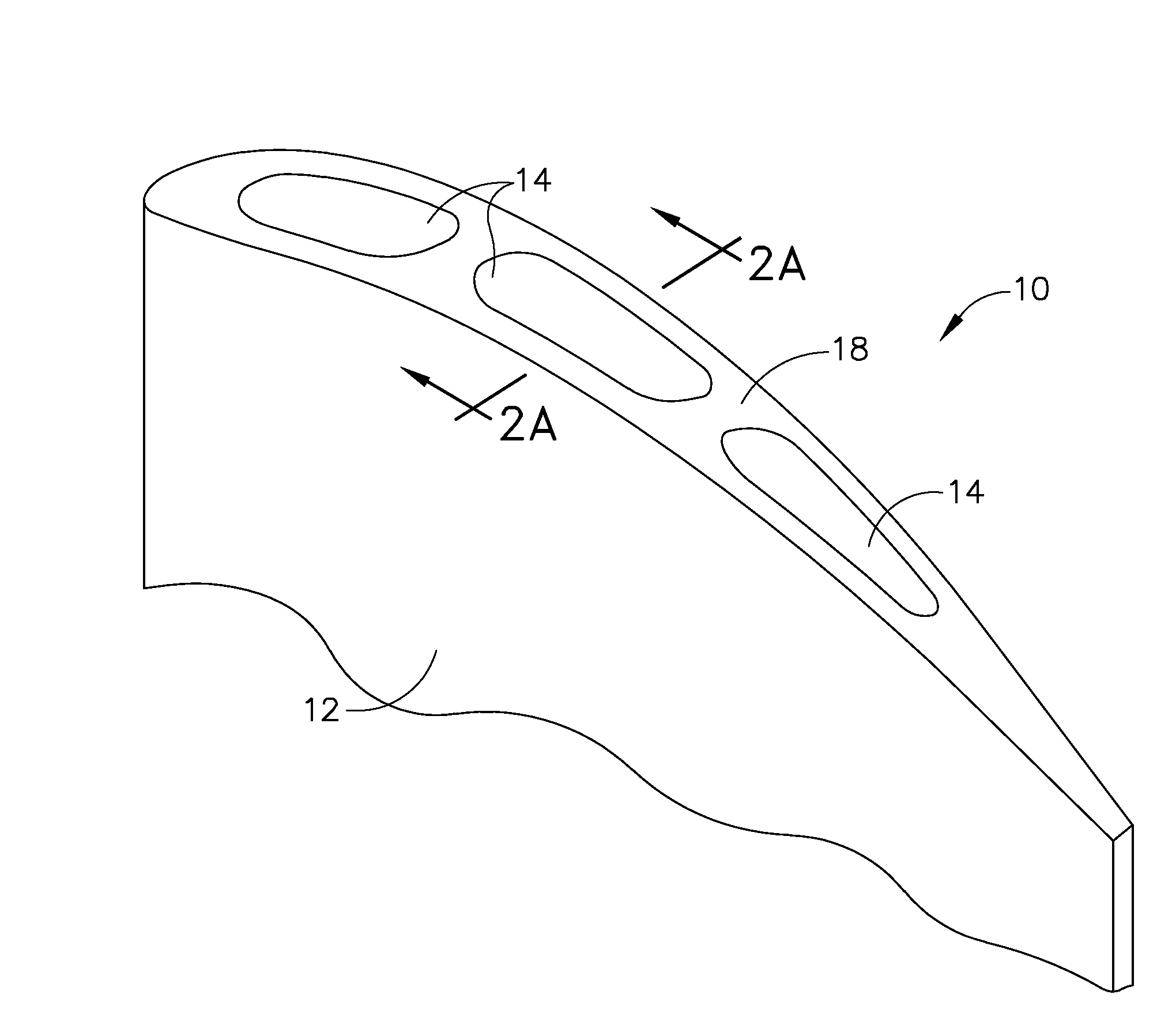
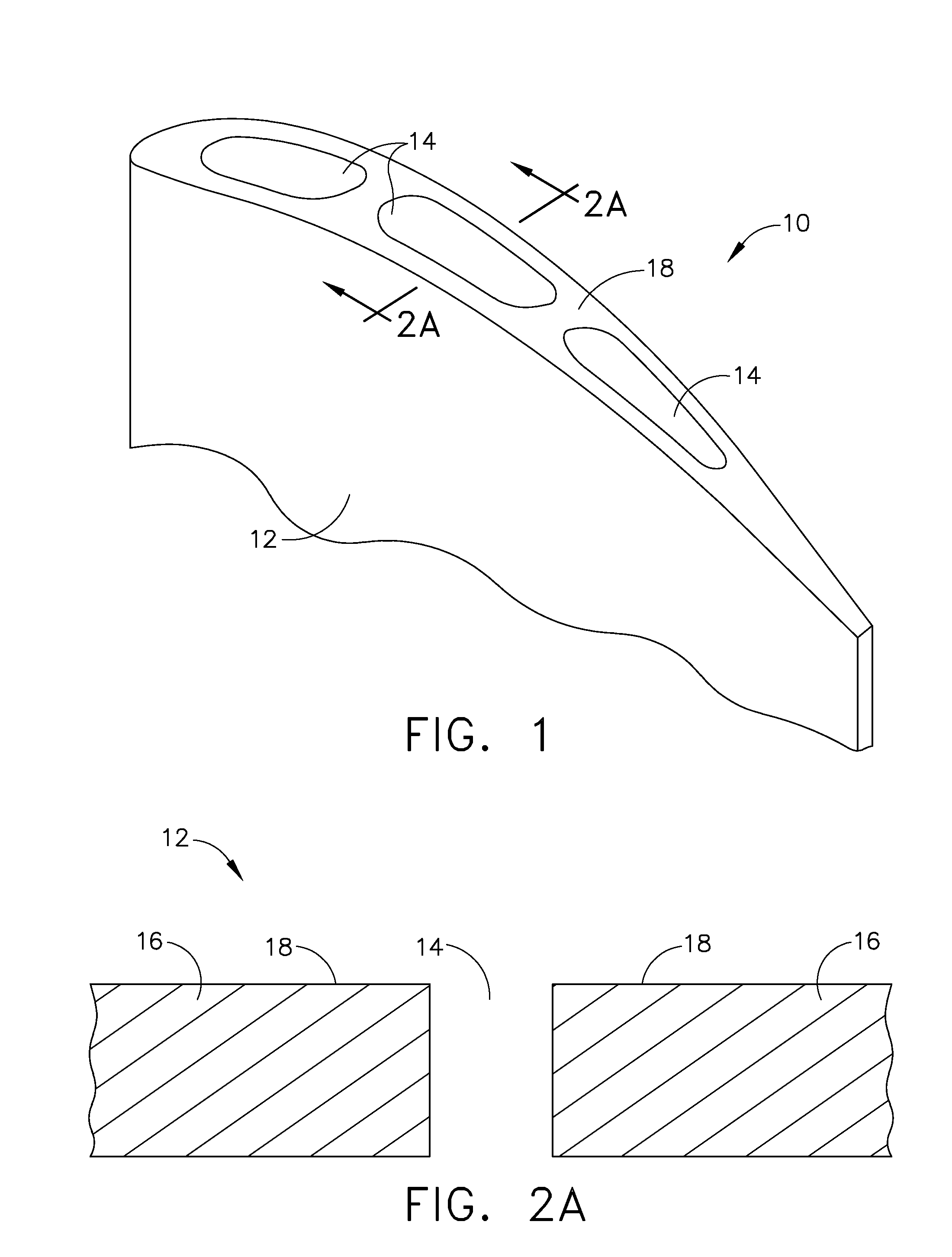
[0014]FIG. 1 represents a perspective view of the tip region 12 of a component 10, such as a bucket, nozzle, or other hot gas path component of a gas turbine. As such, the component 10 is preferably a directionally-solidified or single-crystal casting formed of a high-temperature material, notable examples of which include nickel-base superalloys such as René N4, René N5 , René 108, GTD-111®, GTD-444° and IN-738. René N4, René N5 , René 108, GTD-111® and GTD-444® are gamma prime-strengthened nickel-based superalloys whose compositions are reported in various literature, including U.S. Pat. Nos. 4,810,467, 5,154,884, 5,399,313, 6,074,602, 6,416,596, 6,428,637, and others. The nominal composition of IN-738 is reported as, by weight, about 16% chromium, 8.5% cobalt, 1.75% molybdenum, 2.6% tungsten, 1.75% tantalum, 0.9% niobium, 3.4% aluminum, 3.4% titanium, 0.10% zirconium, 0.01% boron, 0.17% carbon, the balance nickel and impurities. Notably, each ofthese nickel-base materials nominal...


PUM

PropertyMeasurementUnit
Fractionaaaaaaaaaa
Fractionaaaaaaaaaa
Fractionaaaaaaaaaa

Abstract

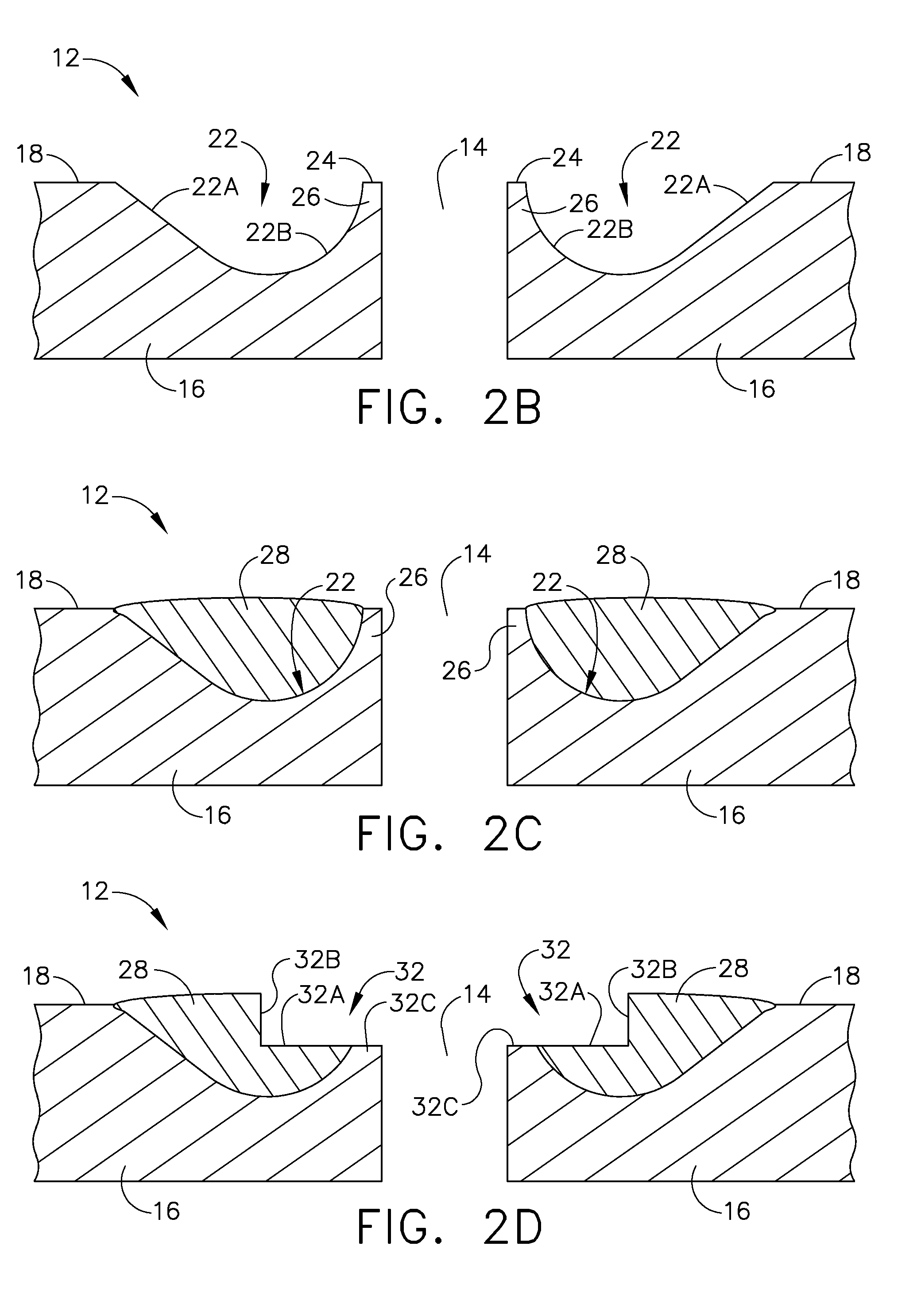
A process for closing an opening in a surface of a component, and components formed thereby. The process entails forming a channel in the component surface so that the channel at least partially surrounds an opening at the component surface. An alloy is then deposited in the channel to form a crack-free deposit in the channel. A step is then machined that intersects the opening and is at least partially formed in the deposit. The step defines a recess that is at least partially surrounded by a peripheral portion of the deposit and has a surface recessed into the component surface. A cap is placed in the recess and welded to the peripheral portion of the deposit to define a weld joint that completely closes the opening. The surface of the weld joint is then machined to form a machined surface that is substantially flush with the component surface.

Description

BACKGROUND OF THE INVENTION[0001]The present invention relates to methods for closing holes in components that operate at high temperatures, such as holes located at the tips of gas turbine buckets. More particularly, this invention relates to a process of filling holes in castings formed of alloys that are prone to strain age cracking when attempting to fill such holes by conventional welding techniques.[0002]Components of gas turbines, such as buckets (blades), nozzles (vanes), and other hot gas path components, are typically formed of nickel, cobalt or iron-base superalloys with desirable mechanical and environmental properties for turbine operating temperatures and conditions. Because the efficiency of a gas turbine is dependent on its operating temperatures, there is a demand for components, and particularly turbine buckets and nozzles, that are capable of withstanding increasingly higher temperatures. As the maximum local temperature of a superalloy component approaches the me...

Claims


Application Information

Patent Timeline
IPC IPC(8): B23K9/04
CPCB23K10/027B23K2201/001F01D5/147B22C21/14F05D2230/21F05D2230/232C22C19/07B23K26/3213B23K26/345B23K35/30B23K35/3066C22C19/055C22C19/056F05D2230/10B23K26/32B23K26/342B23K2103/18B23K2103/26B23K2101/001
Inventor CUI, YANMUKIRA, GITAHI CHARLESKOTTILINGAM, SRIKANTH CHANDRUDU
Owner GENERAL ELECTRIC CO
Learn More