R-t-b-type sintered magnet and method for production thereof

a sintered magnet and r-t-b technology, applied in the field of r-t-b-based sintered magnets, can solve the problems of increased r mole fraction in material alloys, decreased remanence, and inability to produce liquid phases smoothly, etc., to achieve excellent thermal resistance, increase coercivity, and high remanence

Active Publication Date: 2011-02-03
HITACHI METALS LTD
View PDF8 Cites 40 Cited by
  • Summary
  • Abstract
  • Description
  • Claims
  • Application Information

AI Technical Summary

Benefits of technology

[0028]An R-T-B based sintered magnet according to the present invention can have increased coercivity while maintaining high remanence. As a result, the sintered magnet can exhibit excellent thermal resistance without being easily demagnetized with heat.

Problems solved by technology

With such an insufficient R mole fraction, a liquid phase (i.e., an R-rich phase) would not be produced smoothly, even though such a liquid phase must be produced to advance the sintering process.
To overcome such a problem, however, there is no choice but to increase the R mole fraction in the material alloy too much to avoid a decrease in remanence.
That is why even if the pulverized powder particle size were simply decreased, a high-performance magnet could not still be produced.
On top of that, if the overall surface area of a powder compact increased as the finely pulverized powder particle size decreases, then the interfacial energy would increase so much that an abnormal grain growth would arise easily during the sintering process, thus making it difficult to obtain a sintered magnet that has a desired uniform and fine texture.
Consequently, high coercivity cannot be achieved just by decreasing the finely pulverized powder particle size.
In any case, the amounts of impurities will naturally increase and a composition with a high R mole fraction cannot help being adopted.
However, as such a different phase that will not contribute to improving the magnetic properties must be used according to such a method, the remanence will decrease inevitably, and therefore, it is difficult to apply such a method to making a high-performance magnet.
That is why it is also difficult to achieve high remanence, or make a high-performance magnet, by such a technique.
However, as a compound phase that will not contribute to improving the magnetic properties is included in the magnet, the remanence should naturally decrease, and the performance of the magnet can be improved only to a limited degree.
However, Patent Document No. 7 does not mention at all a specific means for pulverizing the powder to the particle size disclosed using a jet mill without increasing the amounts of impurities such as oxygen.
Furthermore, Patent Document No. 7 does disclose the amount of oxygen in the finely pulverized powder but does not disclose the composition of the sintered magnet or the amounts of impurities such as oxygen.
As a result, a lot of rare-earth element R (such as 31.5 mass % of Nd as mentioned in specific examples of Patent Document No. 7) must be used, and such a technique cannot be used to make a high-performance magnet.

Method used


Image

  • R-t-b-type sintered magnet and method for production thereof
  • R-t-b-type sintered magnet and method for production thereof
  • R-t-b-type sintered magnet and method for production thereof

Examples


example 1

[0107]A melt of a material alloy was obtained by mixing together Pr and Nd with a purity of 99.5% or more, Tb and Dy with a purity of 99.9% or more, electrolytic iron and low-carbon ferroboron as main ingredients, along with additive elements (Co and / or M) added as either pure metals or alloys with Fe, and then melting the mixture. The melt thus obtained was quenched by strip casting process, thereby obtaining a plate alloy with a thickness of 0.1 to 0.3 mm.

[0108]Next, that alloy was decrepitated with hydrogen in a pressurized hydrogen atmosphere, heated to 600° C. within a vacuum, and then cooled. Thereafter, the alloy was classified with a sieve to obtain a coarse alloy powder with particle sizes of 425 μm or less.

[0109]Subsequently, the coarse alloy powder was subjected to a dry pulverization process using a jet mill within a nitrogen gas jet, of which the oxygen concentration was controlled to 50 ppm or less, thereby obtaining an intermediate finely pulverized powder with a part...

example 2

[0118]A melt of a material alloy was obtained by mixing together Pr and Nd with a purity of 99.5% or more, Tb and Dy with a purity of 99.9% or more, electrolytic iron and pure boron as main ingredients, along with (Co and / or M) added as either pure metals or alloys with Fe, and then melting the mixture. The melt thus obtained was quenched by strip casting process, thereby obtaining a plate alloy with a thickness of 0.1 to 0.3 mm.

[0119]Next, that alloy was decrepitated with hydrogen in a pressurized hydrogen atmosphere, heated to 600° C. within a vacuum, and then cooled. Thereafter, the alloy was classified with a sieve to obtain a coarse alloy powder with particle sizes of 425 μm or less.

[0120]Subsequently, the coarse alloy powder was subjected to a dry pulverization process using a jet mill with a rotary classifier within an Ar gas jet. In this process step, the rotational frequency of the classifier was varied and the pressure of the pulverization gas was set to be 0.98 MPa, which...

example 3

[0130]A melt of a material alloy was obtained by mixing together Pr and Nd with a purity of 99.5% or more, Tb and Dy with a purity of 99.9% or more, electrolytic iron and pure boron as main ingredients, along with additive elements (Co and / or M) added as either pure metals or alloys with Fe, and then melting the mixture. The melt thus obtained was quenched by strip casting process, thereby obtaining a plate alloy with a thickness of 0.1 to 0.3 mm.

[0131]Next, that alloy was decrepitated with hydrogen in a pressurized hydrogen atmosphere, heated to 600° C. within a vacuum, and then cooled. Thereafter, the alloy was classified with a sieve to obtain a coarse alloy powder with particle sizes of 425 μm or less.

[0132]Subsequently, the coarse alloy powder was subjected to a dry pulverization process using a jet mill within an He gas jet, thereby obtaining a fine powder having a particle size D50 of 2.8 μm or less and an oxygen content of 0.2 mass % or less. This particle size was obtained ...


PUM

PropertyMeasurementUnit
equivalent circle diametersaaaaaaaaaa
particle sizeaaaaaaaaaa

Abstract

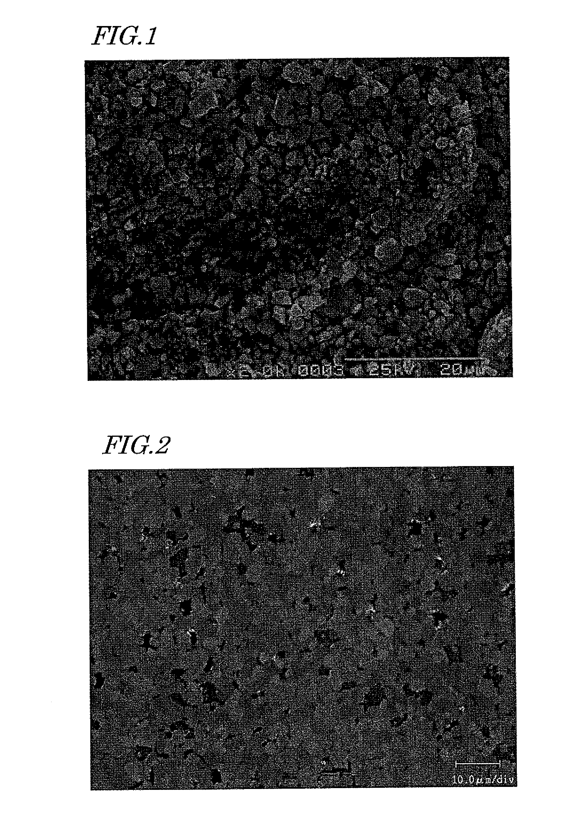
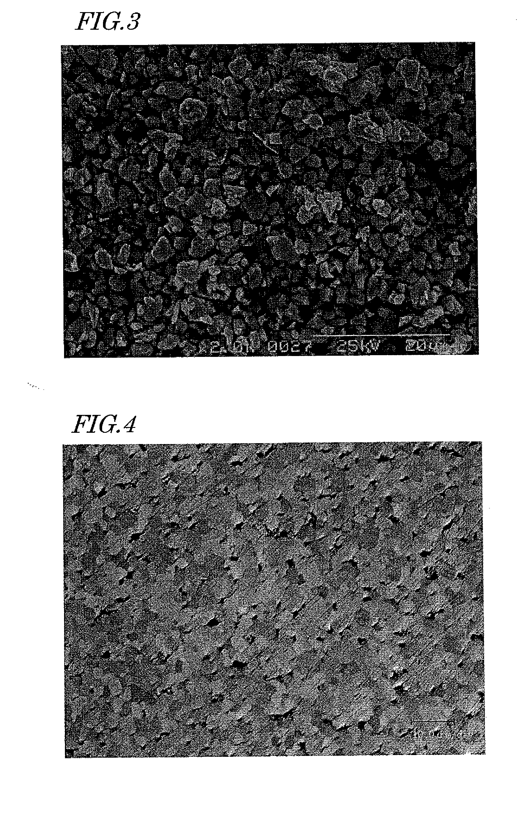
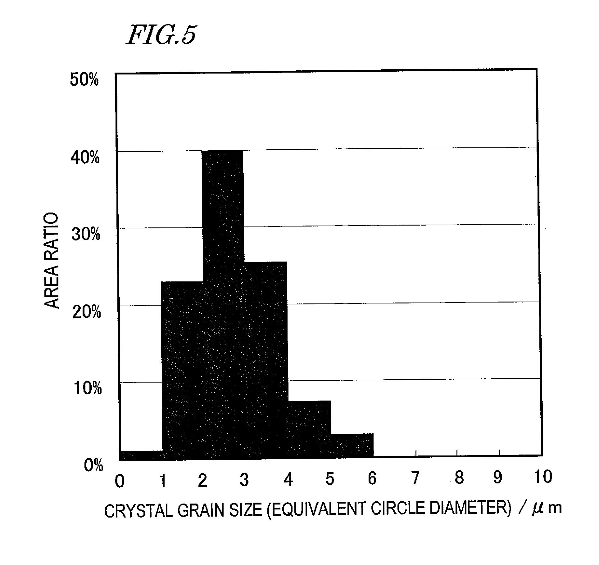
An R-T-B based sintered magnet according to the present invention has a composition including: 27.3 mass % to 29.5 mass % of R; 0.92 mass % to 1 mass % of B; 0.05 mass % to 0.3 mass % of Cu; 0.02 mass % to 0.5 mass % of M; and T as the balance, and has an oxygen content of 0.02 mass % to 0.2 mass %. The main phase of the sintered magnet is an R2T14B type compound. The crystal grain size of the main phase is represented by an equivalent circle diameter of 8 μm or less. And crystal grains with equivalent circle diameters of 4 μm or less account for at least 80% of the overall area of the main phase.

Description

TECHNICAL FIELD[0001]The present invention relates to an R-T-B based sintered magnet with high coercivity, which can be used effectively to make a motor, among other things.BACKGROUND ART[0002]It is known that the crystal grain size of an R2T4B compound (where R is at least one of the rare-earth elements, T is either Fe alone or Fe and Co, and B is boron), which is included as a main phase in an R-T-B based sintered magnet, is one of the factors that determine the performance of the magnet. And it is generally known that the coercivity can be increased by reducing the size of crystal grains in the sintered magnet.[0003]However, if the size of finely pulverized powder particles (i.e., the diameter of the powder particles) were reduced to decrease the size of crystal grains in a sintered magnet, then the overall surface area of the powder particles would increase, and therefore, the amounts of impurities such as oxygen to be adsorbed onto the surface of the particles would also increa...

Claims


Application Information

Patent Timeline
Patent Type & Authority Applications(United States)
IPC IPC(8): H01F7/02B22F3/12
CPCB22F2998/10B22F2999/00H01F41/0266H01F1/0577C22C2202/02C22C38/16C22C38/10C22C38/005C22C33/0278C22C38/001C22C38/002B22F9/04B22F3/02B22F3/10B22F2202/05H01F1/0573H01F1/0571H01F41/0273
Inventor KUNIYOSHI, FUTOSHIISHII, RINTARO
Owner HITACHI METALS LTD
Why Eureka
Try Eureka