Biomedical electrode configuration for suppressing movement artifact

a biomedical electrode and electrode configuration technology, applied in the field of sensing biopotentials generated, can solve the problems of particularly problematic movement artifacts, especially problematic effects, and overwhelm the amplitude of semg signals, and achieve the effect of suppressing movement induced electrical artifacts

Active Publication Date: 2011-02-03
ALTECH INDS
View PDF16 Cites 25 Cited by
  • Summary
  • Abstract
  • Description
  • Claims
  • Application Information

AI Technical Summary

Benefits of technology

[0016]A fixed framework may be coupled to the substrate, in which the substrate is a body-directed electrically insulating bottom surface of the framework, forming an electrode to body interface. A symmetrical arrangement of two signal input and two signal reference contacts may be retained by the fixed framework, each having a contact surface projecting from the bottom surface and a coupling surface projecting above the

Problems solved by technology

Movement artifact can be particularly problematic as the change in half-cell potential can exhibit large (>50 mV) voltage deviations which overwhelm the amplitude of the sEMG signal.
This effect can be especially problematic when the electrolytic skin interface exhibits high impedance resulting from the lack of suitable moisture between the electrode contact and the skin.
Highly conductive aqueous salt solutions or hydrophilic gels applied to the contacts surface act to improve the electrolytic skin interface by augmenting the nature moisture present on the skins surface to stabilize and reduce skin impedance, however these materials can create large half-cell potentials, and if not properly applied, can leak to form low impedance bridges between electrode contacts thereby “shorting out” the desired bio-potential signal.
Electrodes formed as an insulating capacitive plate overcome some of the problems associated with half-cell potential created when using ohmic electrodes, but are subject to the triboelectric charge effect on dry stratum corneum, and therefore subject to movement artifact and static discharge when placed under clothing.
However, in compliant or flexible electrode skin interface design

Method used


Image

  • Biomedical electrode configuration for suppressing movement artifact
  • Biomedical electrode configuration for suppressing movement artifact
  • Biomedical electrode configuration for suppressing movement artifact

Examples


Embodiment Construction

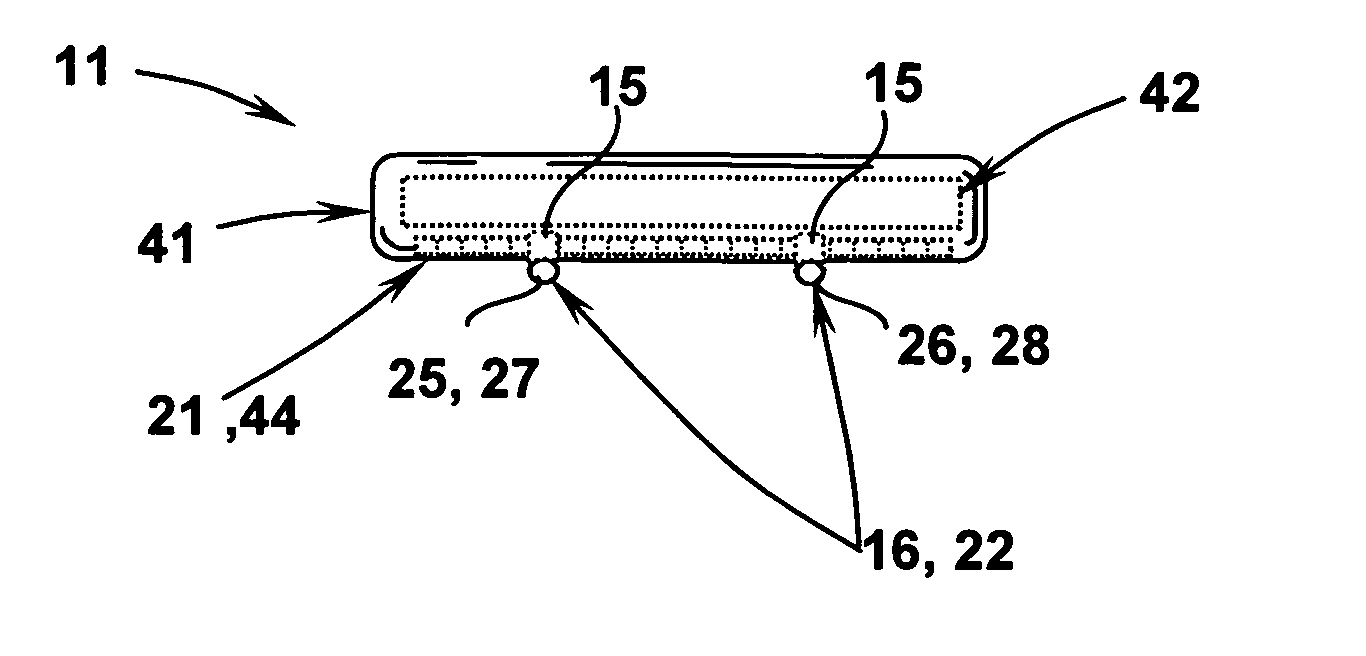
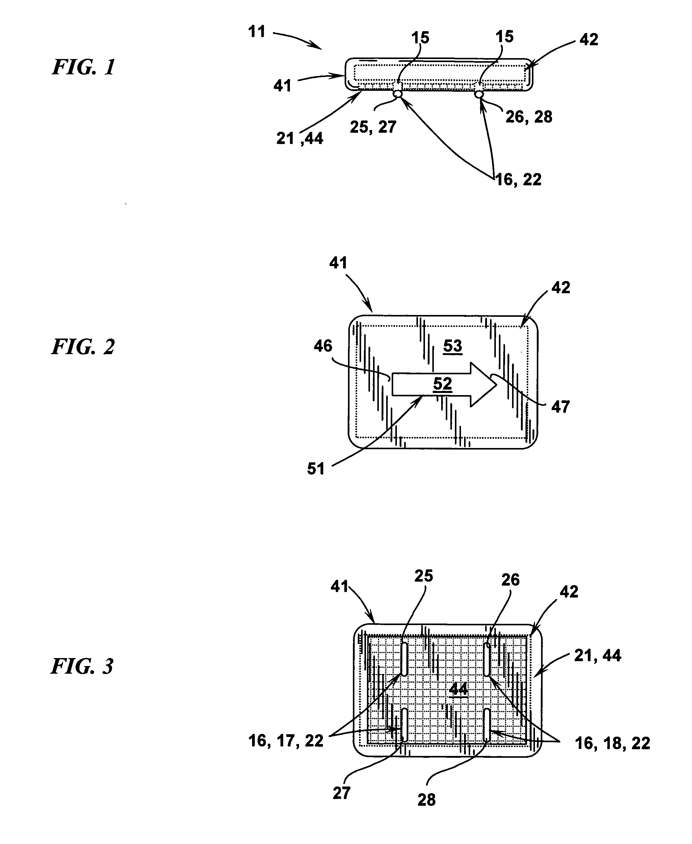
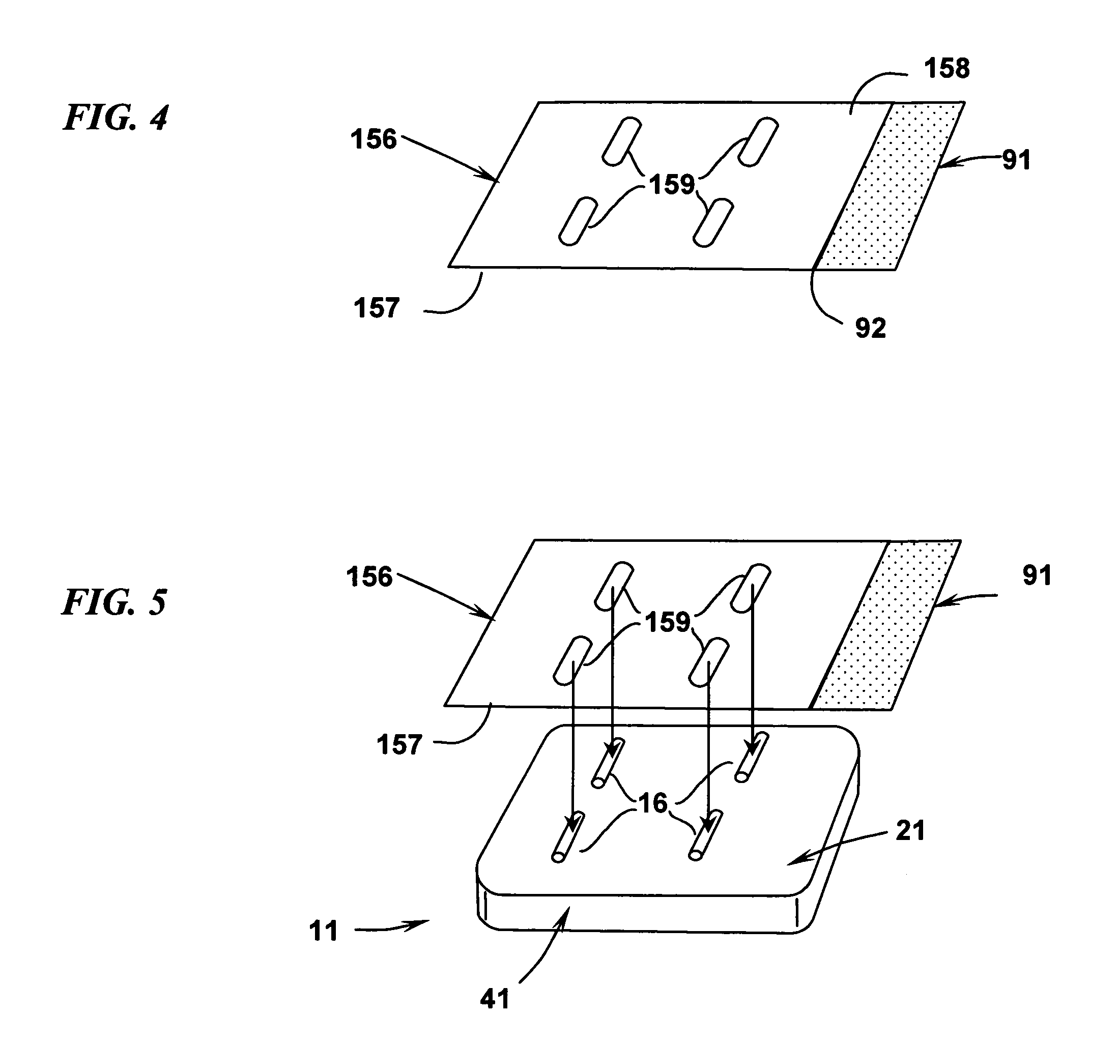
[0038]A biomedical sensor 11 includes a molded case 41 that retains a preamplifier and associated electronics 42 for wireless transmission of the detected signal as illustrated in FIG. 1. Disposed on the bottom surface 21 of the case 41, or other type of framework, may be a rigid fixed substrate surface 44. Disposed on the substrate surface 44 of the case 41 (FIG. 3) may be a symmetrical, parallel array of cylindrical bar contacts 16 each retained by a projecting portion 15 electrically interconnected with the preamplifier 42. Included among the contacts 16 are two pairs of contacts 17, 18. One pair of contacts 17 may include a positive signal detection contact 25 and a reference contact 27. A second pair of contacts 18 may include a negative signal detection contact 26 and a reference contact 28. The two signal detection contacts 25, 26 and the two reference contacts 27, 28 may be linearly aligned with respect to the case indicia 51 disposed on the top surface 53 of the case 41 ill...


PUM


Abstract

A biomedical sensor for detecting EMG signals may include a non-conducting fixed framework supporting a symmetrical arrangement of four electrode surfaces, configured as two signal detection contacts, each with a respective associated signal reference contact. The mechanical and electrical configuration act together to suppress movement artifact.

Description

RELATED APPLICATIONS[0001]This application claims priority to U.S. Provisional App. No. 61 / 271,930, filed Jul. 28, 2009, which is incorporated herein by reference.TECHNICAL FIELD[0002]This application relates to the field of sensing bio-potentials generated within a living body and, more particularly, to sensors placed on the surface of the skin for detecting the electrical activity from muscles.BACKGROUND OF THE INVENTION[0003]Depolarization potentials created during a muscle fiber contraction generate an electrical field gradient which propagates in a direction along the fibers throughout the volume conductor comprised of the muscle, the surrounding tissue, and skin layers. Electrodes placed on the skins surface allow for the non-invasive detection of this electrical field gradient providing the temporal summation of the propagating depolarization potentials of the active muscle fibers in the underlying vicinity of the electrode. The resulting voltage on the skin's surface is term...

Claims


Application Information

Patent Timeline
IPC IPC(8): A61B5/04A61B5/296
CPCA61B5/0488A61B5/7214A61B5/0492A61B5/296A61B5/389
Inventor GILMORE, L. DONALDDE LUCA, GIANLUCADE LUCA, CARLO J.
Owner ALTECH INDS
Why Eureka
Try Eureka