Syngas cleanup section with carbon capture and hydrogen-selective membrane

a technology of hydrogen-selective membrane and syngas, which is applied in the direction of hydrogen separation using liquid contact, machine/engine, separation process, etc., can solve the problems of high capital cost, hampered commercialization of known clean-up technologies (igcc power plants or coal gasification-based power plants), and high capital costs associated

Active Publication Date: 2011-02-10
AIR PROD & CHEM INC
View PDF16 Cites 17 Cited by
  • Summary
  • Abstract
  • Description
  • Claims
  • Application Information

AI Technical Summary

Benefits of technology

[0007]In one aspect of the invention, an apparatus using a hydrogen-selective membrane for carbon capture comprises a water-gas shift reactor configured to receive a syngas from a gasification unit; a first unit operation in flow communication with the water-gas shift reactor, the first unit operation including a first, high permeance membrane with H2/CO2 selectivity in flow communication with the water-gas shift reactor, the first membrane providing a first, H2-rich permeate strea

Problems solved by technology

The commercialization of known “coal-to-hydrogen (H2) and electricity” technologies (IGCC power plants or coal gasification-based power plants) has been hampered by the high capital costs associated with removing the most significant impurities, such as sulfur, present in coal.
However, because of the different operating requirements and parameters of each unit, known clean-up technologies may be expensive.
Moreover, because of the large number of unit operations used, known clean-up technologies generally require large footprints within a plan

Method used


Image

  • Syngas cleanup section with carbon capture and hydrogen-selective membrane
  • Syngas cleanup section with carbon capture and hydrogen-selective membrane
  • Syngas cleanup section with carbon capture and hydrogen-selective membrane

Examples


Embodiment Construction

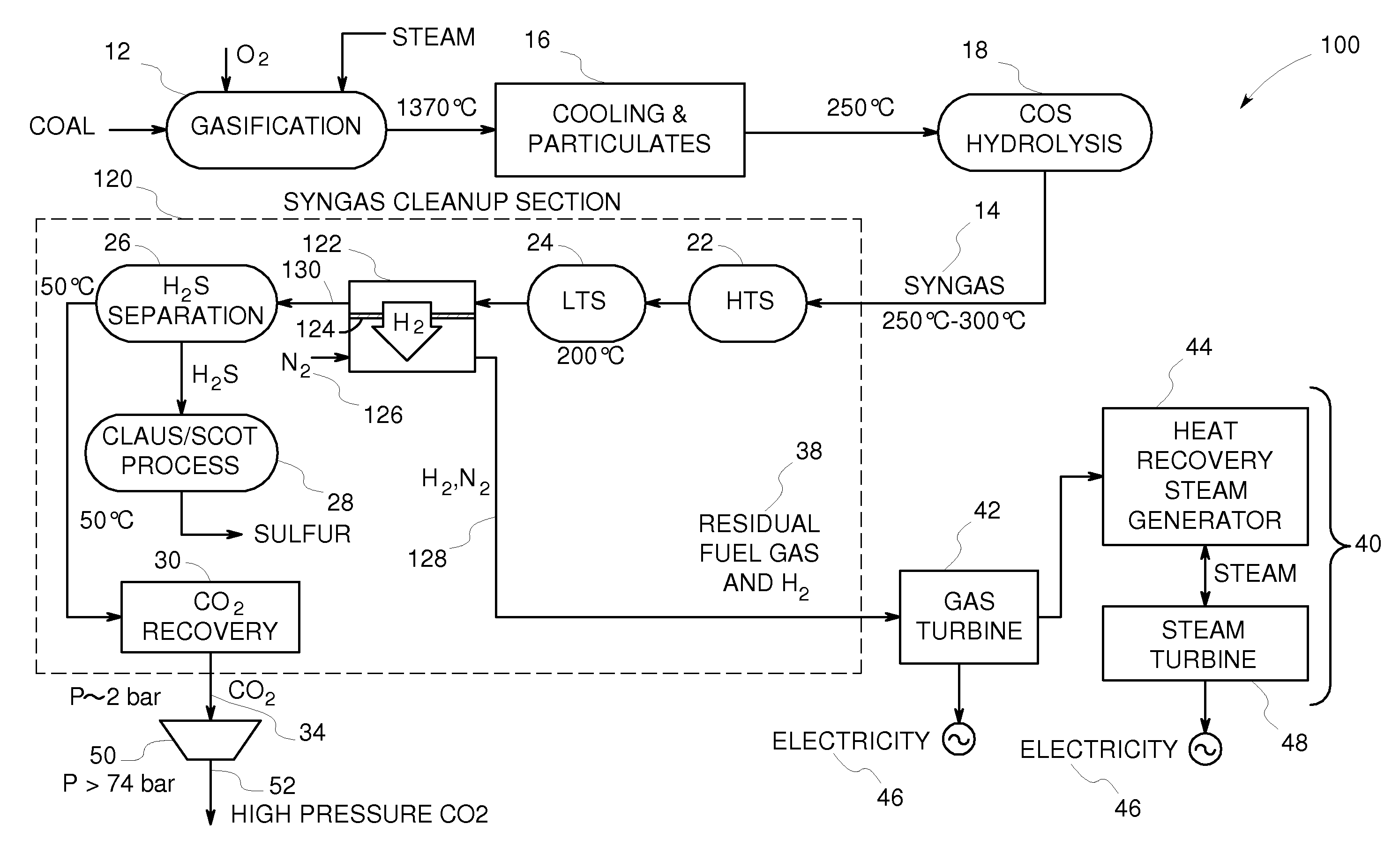
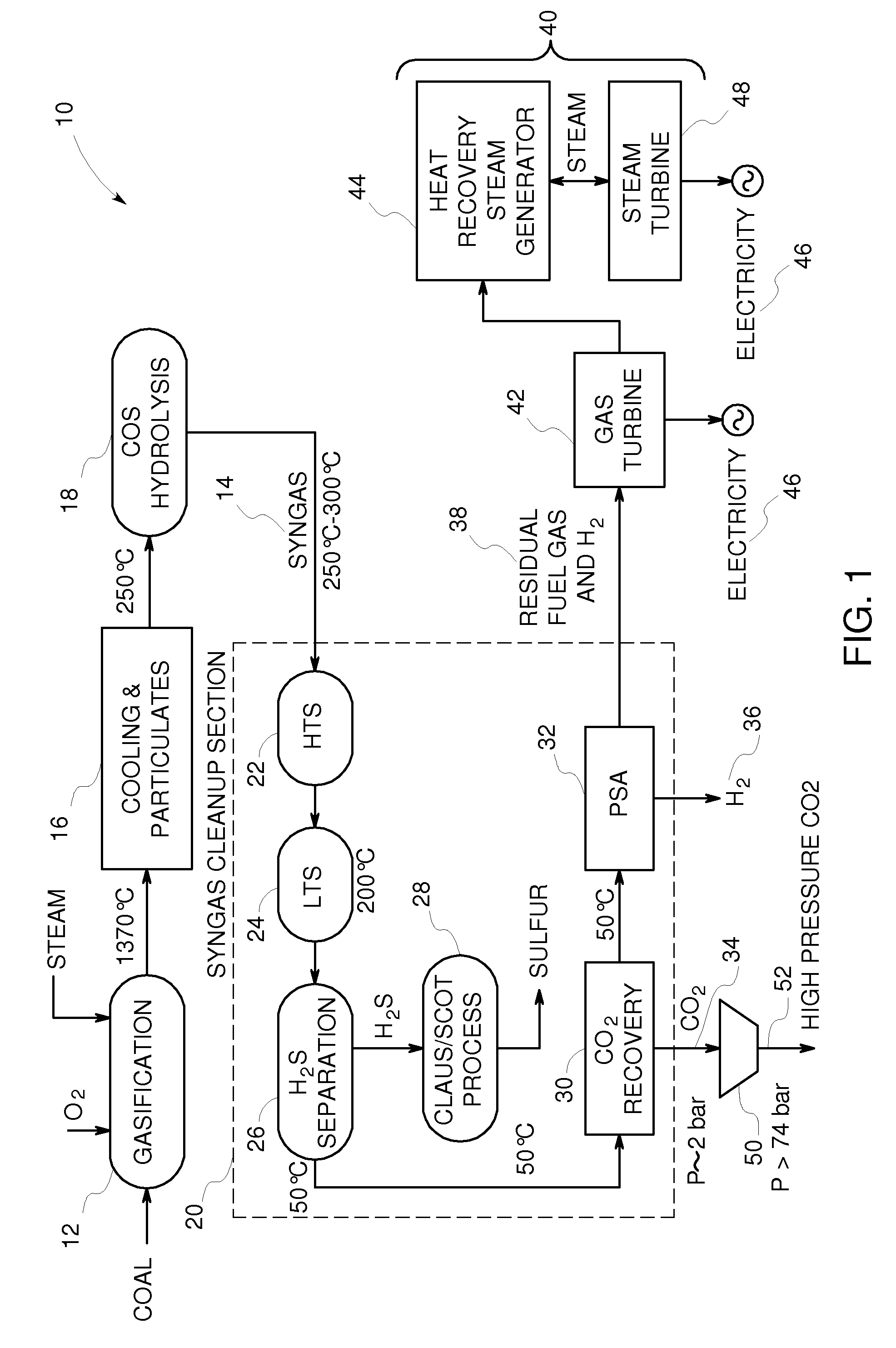
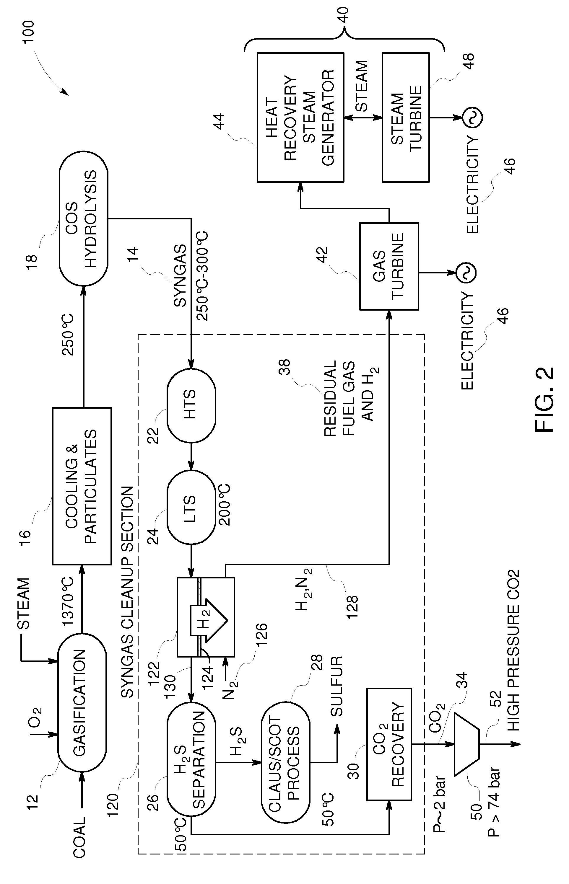
[0020]FIG. 1 is a schematic view of an exemplary polygeneration plant 10 for hydrogen gas (H2) and electricity production with carbon dioxide (CO2) separation. The plant 10 includes a gasification unit 12 that converts a carbon-containing feedstock, oxygen containing material, and high temperature steam or water into a synthesis gas (syngas) stream 14. The carbon-containing feedstock can be in the form of coal, petcoke, biomass, and the like. The gasification unit 12 is in flow communication with a series of syngas coolers 16 configured to remove heat and particulates and with a carbonyl sulfide (COS) hydrolysis unit 18 that is configured to convert COS to hydrogen sulfide (H2S) in the syngas 14. The syngas 14 is then processed through a syngas clean-up section 20 according to the invention.

[0021]In the exemplary embodiment, the clean-up section 20 includes a plurality of individual unit operations including a high-temperature shift (HTS) reactor 22, a low-temperature shift (LTS) re...


PUM


Abstract

A syngas cleanup section includes a water-gas shift reactor, a first operation unit and a second operation unit. The first operation unit includes a high permeance membrane with H2/CO2 selectivity in flow communication with the water-gas shift reactor to provide a H2-rich permeate stream and an H2-poor retentate stream. The second operation unit recovers H2 and CO from the retentate stream to produce a single, CO2-rich product stream, the entire content of which has a minimum pressure of at least about 10.0 bar. In one embodiment, the second operation unit includes a membrane with Knudsen selectivity for permeating H2, CO and CO2. In this embodiment, the permeate streams are combined to produce a H2 and CO-rich fuel stream used by a combined cycle power generation unit to produce electricity, and the retentate stream is sent to a catalytic oxidation unit to produce the CO2-rich product stream. In another embodiment, the second operation unit is the catalytic oxidation unit.

Description

CROSS-REFERENCE TO RELATED APPLICATIONS[0001]This application is related to U.S. application Ser. No. ______ [Docket No. 233,502], and U.S. application Ser. No. ______ [Docket No. 233,522], both filed on the filing date of the present application. The contents of both of these applications is incorporated herein by reference.BACKGROUND OF THE INVENTION[0002]The application of syngas conversion and purification after a gasification process can be used for integrated gasification combined cycle (IGCC) power plants for electricity production from coal. It can also be used for gasification-based power plants that produce multiple products such as hydrogen and electricity from coal, and it is also useful for plants that include carbon dioxide separation. It is also applicable to purification of other hydrocarbon-derived syngas that can be used for electricity production or power, including syngas derived from natural gas, heavy oil, biomass and other sulfur-containing carbon fuels.[0003]...

Claims


Application Information

Patent Timeline
IPC IPC(8): F02C6/18C01B3/12B01J8/00C01B32/50
CPCC01B3/32Y02E20/16C01B3/501C01B3/52C01B2203/0283C01B2203/0288C01B2203/0405C01B2203/044C01B2203/045C01B2203/0455C01B2203/047C01B2203/0475C01B2203/0485C01B2203/0495C01B2203/06C01B2203/145C01B2203/146C01B2203/84Y02E20/18C01B3/50Y02P30/00
Inventor KU, ANTHONY YU-CHUNGACHARYA, HARISH RADHAKRISHNAKULKARNI, PARAG PRAKASHMILLER, SCOTT MICHAELLIVINGOOD, III, WILLIAM COOK
Owner AIR PROD & CHEM INC
Why Eureka
Try Eureka