Flat cutting tool

a cutting tool and flat technology, applied in the direction of manufacturing tools, soldering devices, saw chains, etc., can solve the problems of increasing material costs, affecting cutting properties such as rigidity and abrasion resistance of cutting tools, and difficult to control uneven thickness of surface layers, etc., to achieve a higher the effect of high degree of precision and stability

Inactive Publication Date: 2011-02-10
KANEFUSA HAMONO KOUGIYOU KK
View PDF16 Cites 8 Cited by
  • Summary
  • Abstract
  • Description
  • Claims
  • Application Information

AI Technical Summary

Benefits of technology

[0011]Further, in the present invention, it is preferable that the cutting edge is formed on the surface layer after the surface layer is hardened to a hardness suitable for the cutting tool by quenching and tempering heat treatment of the blade member. This allows a cutting edge to be formed on the surface layer hardened to a hardness suitable for the cutting tool. As a result, the cutting edge is formed with a high degree of precision and stability.
[0012]In the present invention, it is also preferable that after the surface layer is hardened to a hardness suitable for the cutting tool by quenching and tempering heat treatment of the blade member, and then at least the lower layer side of the blade member is joined to a separate base member using a brazing filler metal or an adhesive agent, the cutting edge is formed on the surface layer. This allows a cutting edge to be formed on the surface layer with the blade member hardened to a hardness suitable for the cutting tool being joined to the base member. As a result, the cutting edge is formed with a higher degree of precision and stability.

Problems solved by technology

If the thickness is less than 0.1 mm, it becomes difficult to control unevenness in thickness of the surface layer at the time of finishing a flat cutting tool.
As a result, the cutting properties such as rigidity and abrasion resistance of the cutting tool are noticeably affected.
An increase in thickness causes a rise in material costs.
Therefore, the force acting on the surface layer at the time of cutting or chipping cannot be sufficiently supported, and the cutting tool becomes easily deformed.
If the thickness is less than 2.5 mm, the strength with which the cutting edge is supported is not sufficient, and as a result, the thickness of the surface layer needs to be increased.
For example, if the blade member is composed of a high-speed tool steel and an alloy steel in two layers without a mild steel layer, warping of a blade member after heat treatment becomes too large to be corrected.
If it is less than 0.5 mm, it becomes difficult to obtain the effect of preventing warping of a blade member after heat treatment.

Method used


Image

  • Flat cutting tool
  • Flat cutting tool
  • Flat cutting tool

Examples


Embodiment Construction

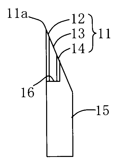
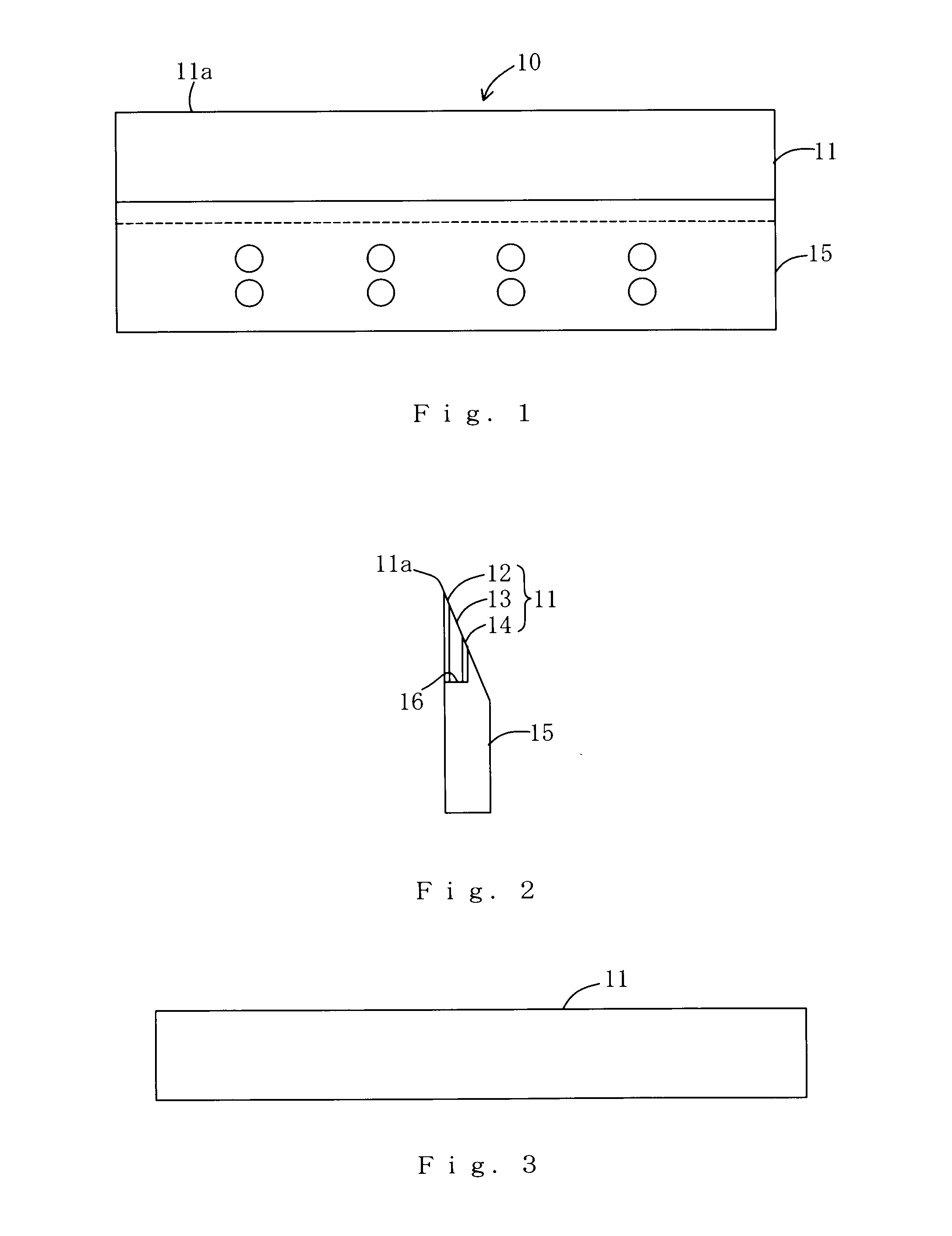
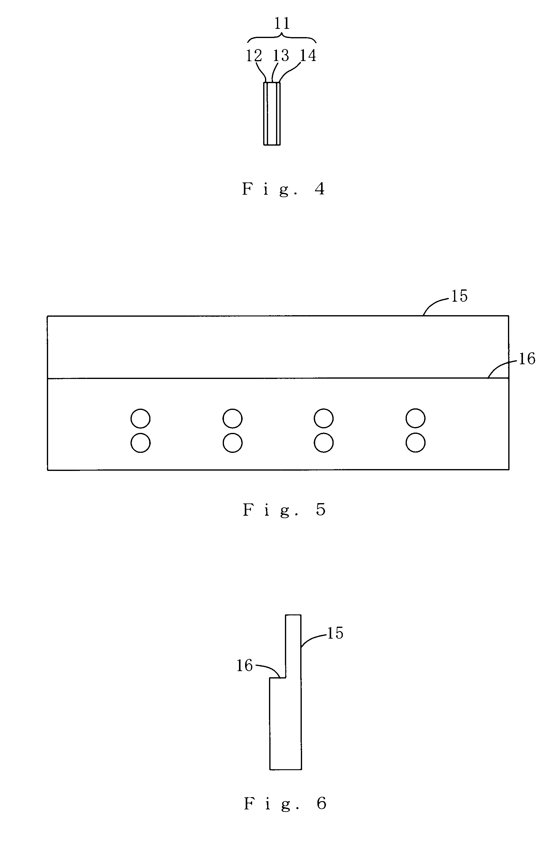
[0022]Hereinafter, one embodiment of the present invention will be described with reference to the drawings. FIGS. 1 and 2 are a front view and a side view of a flat cutting tool used as a cutter blade for cutting superposed sheets of paper in bookbinding according to the embodiment. FIGS. 3 and 4 are a front view and a side view of a blade member, and FIGS. 5 and 6 are a front view and a side view of a base member. The flat cutting tool 10 is formed by fixing a blade member 11 which is a rolled steel plate to a mounting concavity 16 of a base member 15 which is a thick plate made of an ordinary steel, using a brazing filler metal or an adhesive agent, to form a cutting edge 11a on the surface layer 12 side of the blade member 11.

[0023]The blade member 11 is a thin rolled steel plate having a long rectangle shape which is formed by joining a surface layer 12 of a high-speed tool steel with a high degree of hardness, a middle layer 13 of an alloy steel which has a lower quench-harden...


PUM

PropertyMeasurementUnit
thicknessaaaaaaaaaa
thicknessaaaaaaaaaa
thicknessaaaaaaaaaa

Abstract

A flat cutting tool includes a blade member fixed to a mounting concavity of a base member using a brazing filler metal or an adhesive agent to form a cutting edge on a surface layer side of the blade member. The blade member includes a surface layer which is a high-speed tool steel with a high degree of hardness, a middle layer which is an alloy steel having a lower quench-hardenability than the high-speed tool steel, and a lower layer which is a mild steel having little quench-hardenability, which can be formed by forge welding. The blade member can be quenched and tempered, and the surface layer hardened to a hardness suitable for the cutting tool and fixed to the mounting concavity of the base member.

Description

TECHNICAL FIELD[0001]The present invention relates to a flat cutting tool used in a paper cutter for cutting layered paper or a processing machinery for cutting or chipping lumber or plastic, and in particular, to a flat cutting tool including a blade member having a cutting edge made of a high-speed tool steel.BACKGROUND ART[0002]For this kind of flat cutting tool, it is necessary to use expensive steel products, such as a high-speed tool steel with a high degree of hardness, which contain more rare metal such as tungsten and molybdenum at the blade edge in order to improve a cutting performance. The manufacturing cost of such a flat cutting tool, however, is very high because the whole cutting tool is formed of expensive high-speed tool steels. In addition, a significant rise in prices associated with the recent decrease of rare metal resources has led to an increase in price of this kind of flat cutting tool. To solve the above problem, there is a known cutting tool, as described...

Claims


Application Information

Patent Timeline
Patent Type & Authority Applications(United States)
IPC IPC(8): B26D1/00
CPCB23K1/0008B23K20/04B26D2001/0053B26D7/2614B26D2001/002B26D1/0006Y10T83/929
Inventor MIYAZAKI, TOSHIMASAISHIDA, NOBUYUKIWATANABE, HISAYASU
Owner KANEFUSA HAMONO KOUGIYOU KK
Why Eureka
Try Eureka