

Concentrating optical member and concentrating solar power generation module
a technology of solar power generation module and concentrating optical member, which is applied in the direction of pv power plants, lighting and heating apparatus, instruments, etc., can solve the problems of increasing the overall cost, aggravated chromatic aberration, and inability to make efficient use of sunlight, etc., to achieve the effect of improving power generation efficiency, thin, and reducing the working distance between the concentrating optical member and the solar cell elemen
- Summary
- Abstract
- Description
- Claims
- Application Information
AI Technical Summary
Benefits of technology
Problems solved by technology
Method used
Image

Examples
embodiment 1
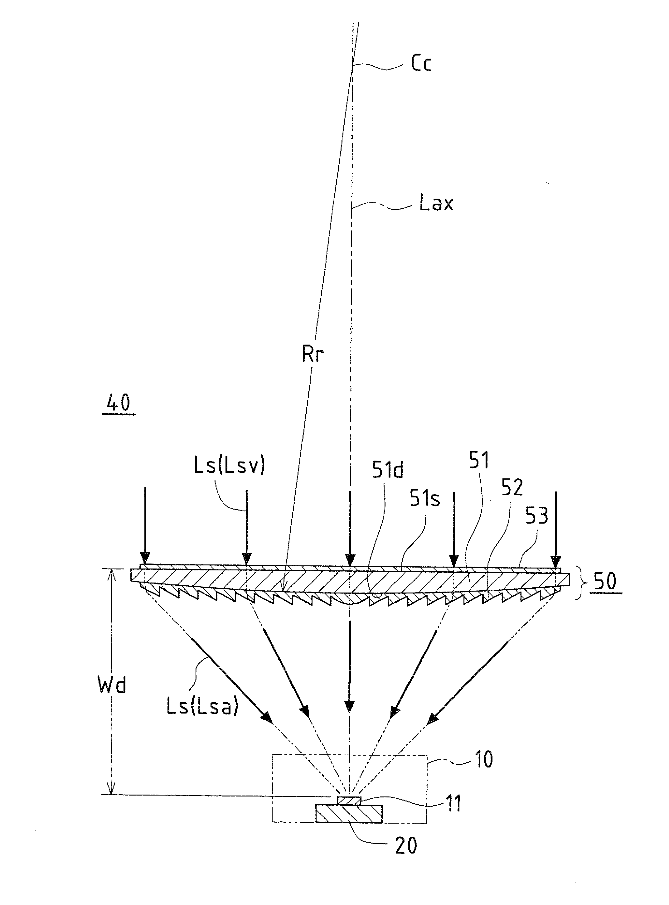
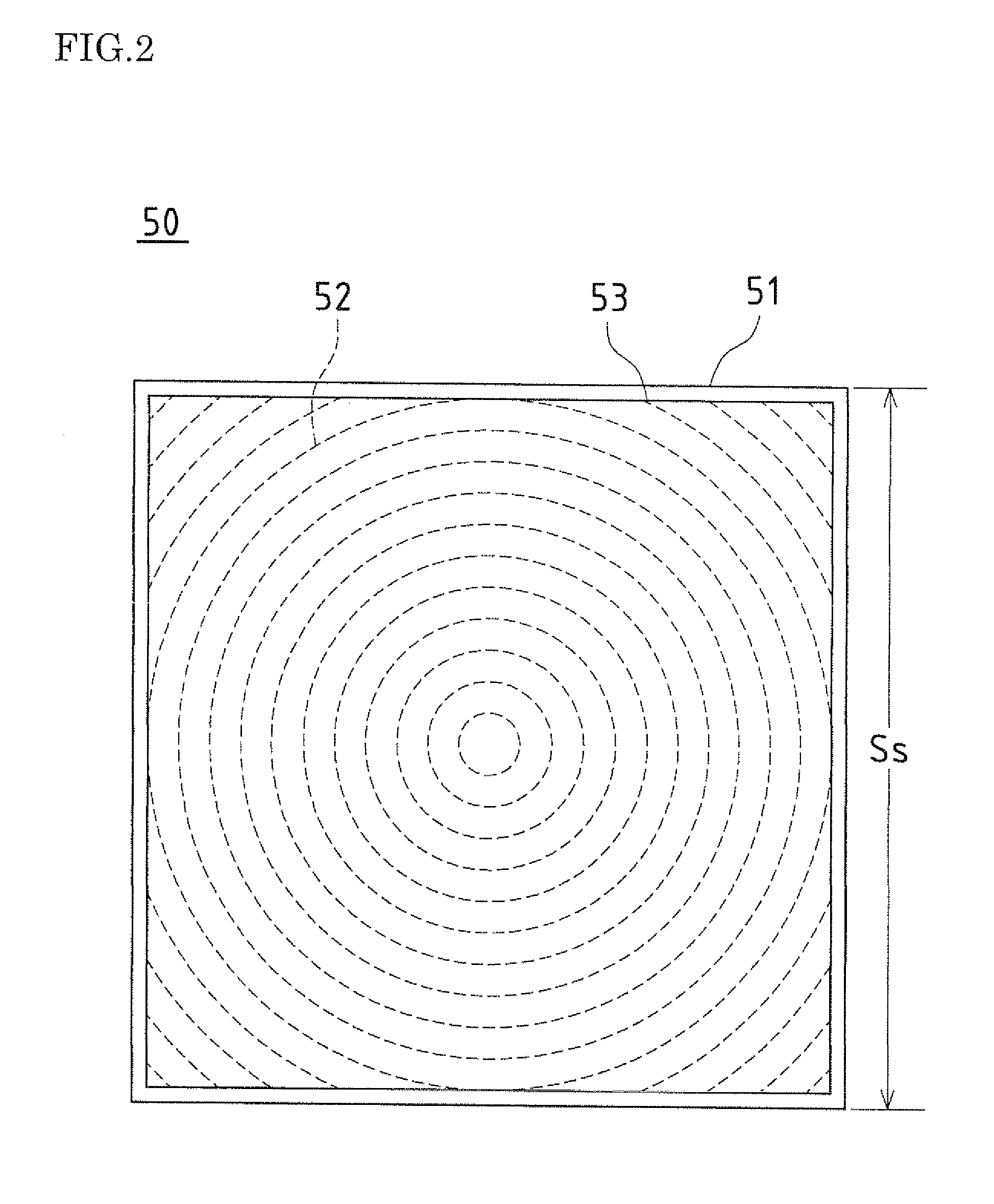
A concentrating optical member and a concentrating solar power generation module according to the present embodiment will be described with reference to FIGS. 1 to 3.
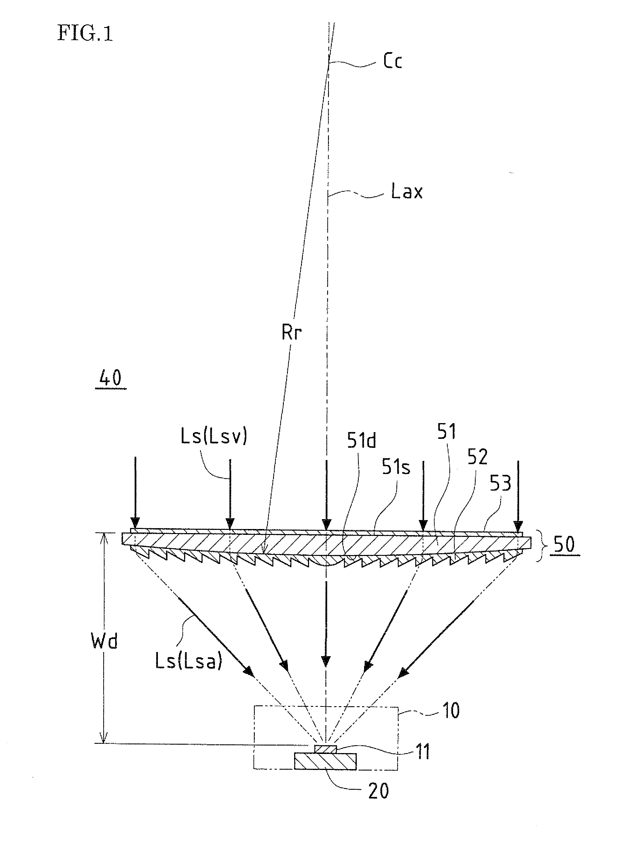
FIG. 1 is a cross-sectional view showing a schematic configuration of a concentrating optical member and a concentrating solar power generation module according to Embodiment 1 of the present invention. FIG. 2 is a plan view of the concentrating optical member shown in FIG. 1 as viewed from the side on which sunlight is incident.
A concentrating optical member 50 according to the present embodiment can be applied to a solar cell 10 that generates power using sunlight Lsa concentrated onto a solar cell element 11, and is configured to concentrate sunlight Lsa onto the solar cell element 11. The solar cell element 11 is mounted on a receiver substrate 20. The configuration of the solar cell 10 will be described in further detail in Embodiment 3.
A concentrating solar power generation module 40 according to the present embod...
embodiment 2
A concentrating optical member and a concentrating solar power generation module according to the present embodiment will be described with reference to FIGS. 4 and 5.
FIG. 4 is a cross-sectional view showing a schematic configuration of a concentrating optical member and a concentrating solar power generation module according to Embodiment 2 of the present invention.
The basic configurations of a concentrating optical member 50 and a concentrating solar power generation module 40 of the present embodiment are the same as those of the concentrating optical member 50 and the concentrating solar power generation module 40 shown in Embodiment 1, and thus the same reference numerals are given, and mainly the differences will be described here.
In the concentrating optical member 50 of the present embodiment, the first optical member 51 having the convex-shaped inner surface 51d shown in FIG. 1 has been replaced with a first optical member 51 having a concave-shaped inner surface 51d.
Speci...
embodiment 3
A solar cell that can be applied to the concentrating optical member and the concentrating solar power generation module according to Embodiments 1 and 2 will be described with reference to FIGS. 6A and 6B as Embodiment 3.
FIG. 6A is a cross-sectional view showing a schematic configuration of a solar cell according to Embodiment 3 of the present invention.
In a solar cell 10 according to the present embodiment, a solar cell element 11 is mounted on a receiver substrate 20. The solar cell 10 includes a sealing frame 31 that is disposed on the outer periphery of the solar cell element 11, a light-transmitting covering plate 32 that is placed on the sealing frame 31 and that is disposed facing the solar cell element 11 so as to protect the solar cell element 11 from the external environment, and a resin sealing portion 33 that resin-seals the space between the solar cell element 11 and the light-transmitting covering plate 32.
In the solar cell 10, a reflecting portion 35 that prevents ir...
PUM
| Property | Measurement | Unit |
|---|---|---|
| refractive index | aaaaa | aaaaa |
| refractive index | aaaaa | aaaaa |
| thickness | aaaaa | aaaaa |
Abstract
Description
Claims
Application Information