Manufacturing Apparatus For Depositing A Material And An Electrode For Use Therein

a technology of manufacturing apparatus and material, which is applied in the direction of plasma welding apparatus, manufacturing tools, coatings, etc., can solve the problems of reducing the heat transfer capability between the coolant and the electrode, fouling of the electrode on the interior surface of the electrode, and affecting so as to prolong the life of the electrode, and maintain the effect of thermal conductivity

Inactive Publication Date: 2011-02-17
HEMLOCK SEMICONDUCTOR CORPORATION
View PDF43 Cites 8 Cited by
  • Summary
  • Abstract
  • Description
  • Claims
  • Application Information

AI Technical Summary

Benefits of technology

[0012]A channel coating is disposed on the interior surface of the electrode for maintaining thermal conductivity between the electrode and the coolant. One advantage of the channel coating is that it is possible to delay fouling of the electrode by resisting the formation of deposits that can form over time due to the interaction between the coolant and the interior surface of the electrode. By delaying fouling, the life of the electrode is extended resulting in a lower production cost and reduced production cycle time of the processed carrier bodies.

Problems solved by technology

A fouling of the electrode occurs on the interior surface of the electrode due to the interaction between the coolant and the interior surface.
The cause of the fouling is dependant on the type of coolant used.
Additionally, the fouling can form as a result of oxidation of the interior surface of the electrode, for example, when the coolant is deionized water or other coolants.
The fouling of the electrode decreases the heat transfer capability between the coolant and the electrode.
The electrode must be replaced when one or more of the following conditions occur: first, when the metal contamination of the material being deposited upon the carrier body exceeds a threshold level; second, when fouling of the contact region of the electrode in the chamber causes the connection between the electrode and the socket to become poor; and third, when excessive operating temperatures for the electrode are required due to fouling of the contact region on the electrode.

Method used


Image

  • Manufacturing Apparatus For Depositing A Material And An Electrode For Use Therein
  • Manufacturing Apparatus For Depositing A Material And An Electrode For Use Therein
  • Manufacturing Apparatus For Depositing A Material And An Electrode For Use Therein

Examples


Embodiment Construction

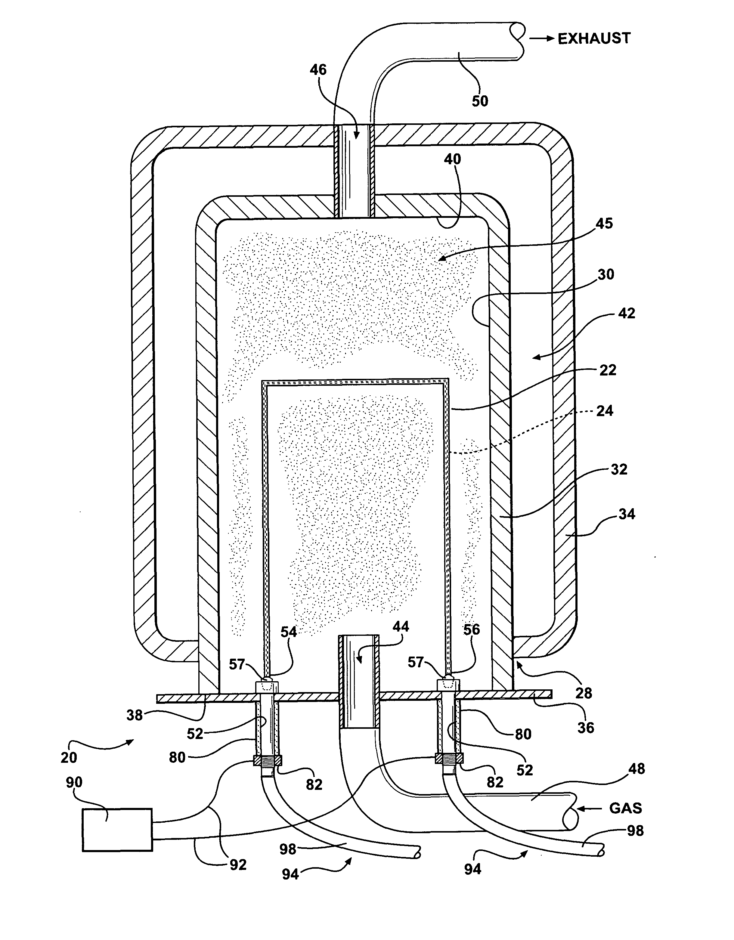
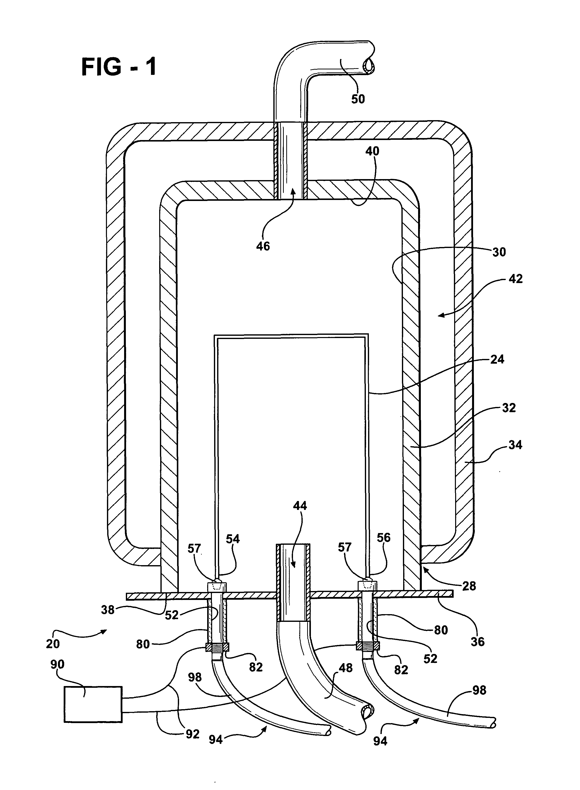
[0024]Referring to the Figures, wherein like numerals indicate like or corresponding parts throughout the several views, a manufacturing apparatus 20 for deposition of a material 22 on a carrier body 24 is shown in FIGS. 1 and 6. In one embodiment, the material 22 to be deposited is silicon; however, it is to be appreciated that the manufacturing apparatus 20 can be used to deposit other materials on the carrier body 24 without deviating from the scope of the subject invention.

[0025]Typically, with methods of chemical vapor deposition known in the art, such as the Siemens method, the carrier body 24 is substantially U-shaped and has a first end 54 and a second end 56 spaced and parallel to each other. A socket 57 is disposed at each of the first end 54 and the second end 56 of the carrier body 24.

[0026]The manufacturing apparatus 20 includes a housing 28 that defines a chamber 30. Typically, the housing 28 comprises an interior cylinder 32, an outer cylinder 34, and a base plate 36....


PUM

PropertyMeasurementUnit
thermal conductivityaaaaaaaaaa
thicknessaaaaaaaaaa
electrical conductivityaaaaaaaaaa

Abstract

The present invention relates to a manufacturing apparatus for deposition of a material on a carrier body and an electrode for use with the manufacturing apparatus. Typically, the carrier body has a first end and a second end spaced from each other. A socket is disposed at each of the end of the carrier body. The apparatus includes a housing that defines a chamber. At least one electrode is disposed through the housing for receiving the socket. The electrode includes an interior surface that defines a channel. The electrode heats the carrier body to a necessary deposition temperature by direct passage of electrical current to the carrier body. A coolant is in fluid communication with the channel of the electrode for reducing the temperature of the electrode. A channel coating is disposed in the interior surface of the electrode for preventing loss of heat transfer between the coolant and the interior surface.

Description

RELATED APPLICATIONS[0001]This application claims priority to and all advantages of U.S. Provisional Patent Application No. 61 / 044,666, which was filed on Apr. 14, 2008.FIELD OF THE INVENTION[0002]The present invention relates to a manufacturing apparatus. More specifically, the present invention relates to an electrode utilized within the manufacturing apparatus.BACKGROUND OF THE INVENTION[0003]Manufacturing apparatuses for the deposition of a material on a carrier body are known in the art. Such manufacturing apparatuses comprise a housing that defines a chamber. Generally, the carrier body is substantially U-shaped having a first end and a second end spaced from each other. Typically, a socket is disposed at each end of the carrier body. Generally, two or more electrodes are disposed within the chamber for receiving the respective socket disposed at the first end and the second end of the carrier body. The electrode also includes a contact region, which supports the socket and, u...

Claims


Application Information

Patent Timeline
Patent Type & Authority Applications(United States)
IPC IPC(8): C23C16/50
CPCC23C16/4418B23K10/02H05B3/03
Inventor DEHTIAR, MAXHILLABRAND, DAVIDKNAPP, THEODOREMCCOY, KEITHMOLNAR, MICHAEL
Owner HEMLOCK SEMICONDUCTOR CORPORATION
Why Eureka
Try Eureka