X-ray tube with passive ion collecting electrode

a technology of ion collecting electrode and x-ray tube, which is applied in the direction of x-ray tube vessel/container, electrical apparatus, electric discharge tube, etc., can solve the problems of unfavorable off-focal radiation, de-stabilizing the focusing, and ions may no longer experience a strong electric pull field, so as to reduce manufacturing and maintenance costs and ensure the effect of safety

Inactive Publication Date: 2011-02-17
KONINKLIJKE PHILIPS ELECTRONICS NV
View PDF12 Cites 19 Cited by
  • Summary
  • Abstract
  • Description
  • Claims
  • Application Information

AI Technical Summary

Benefits of technology

[0008]There may be a need to provide an X-ray tube which at least partially overcomes the above-mentioned problems. Particularly, there may be a need to provide an X-ray tube wherein ions generated within the X-ray tube may be effectively collected and removed from a drift path of the primary electron beam, particularly from a nearly field-less drift path. Furthermore, there may be a need to provide an X-ray tube which is simple in construction thereby reducing manufacturing and maintenance costs.

Problems solved by technology

In such tube designs, due to mirror effects caused by the positively charged anode, a lot of back-directed electrons are redirected again to the anode which is thereby heated in an undesired way and which furthermore creates undesired off-focal radiation from areas spaced apart from the focal spot where the back-directed electrons impact onto the anode.
However, there may arise problems due to ions created from residual gas or target vapour in the intense primary beam and in the shower of back-directed electrons.
However, in recent X-ray tube designs having nearly field-free spaces, the ions may no longer experience a strong electric pull field.
Accordingly, X-ray tubes with a long nearly field-less drift path of the useful electron beam, where the electrostatic field in the vicinity of a major part of the useful electron beam for the generation of X-rays is smaller than the dynamic field generated by the beam space charge, may suffer from substantial ion concentrations in the electron beam which may de-stabilize its focusing.

Method used


Image

  • X-ray tube with passive ion collecting electrode
  • X-ray tube with passive ion collecting electrode
  • X-ray tube with passive ion collecting electrode

Examples


Embodiment Construction

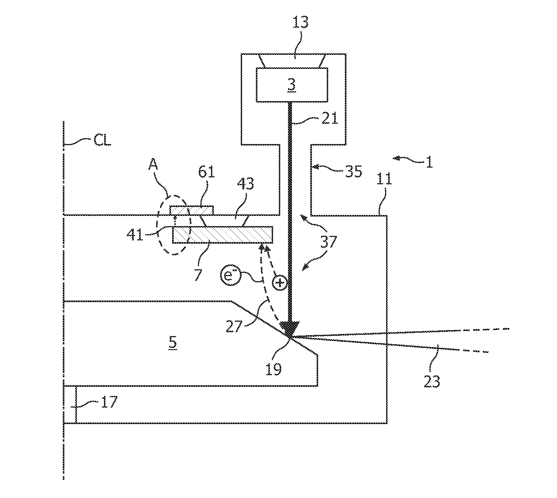
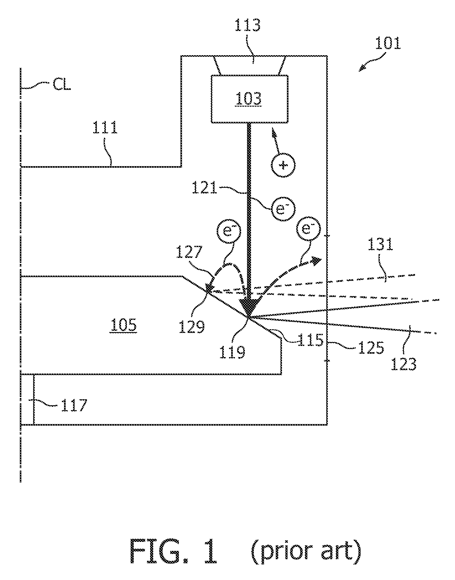
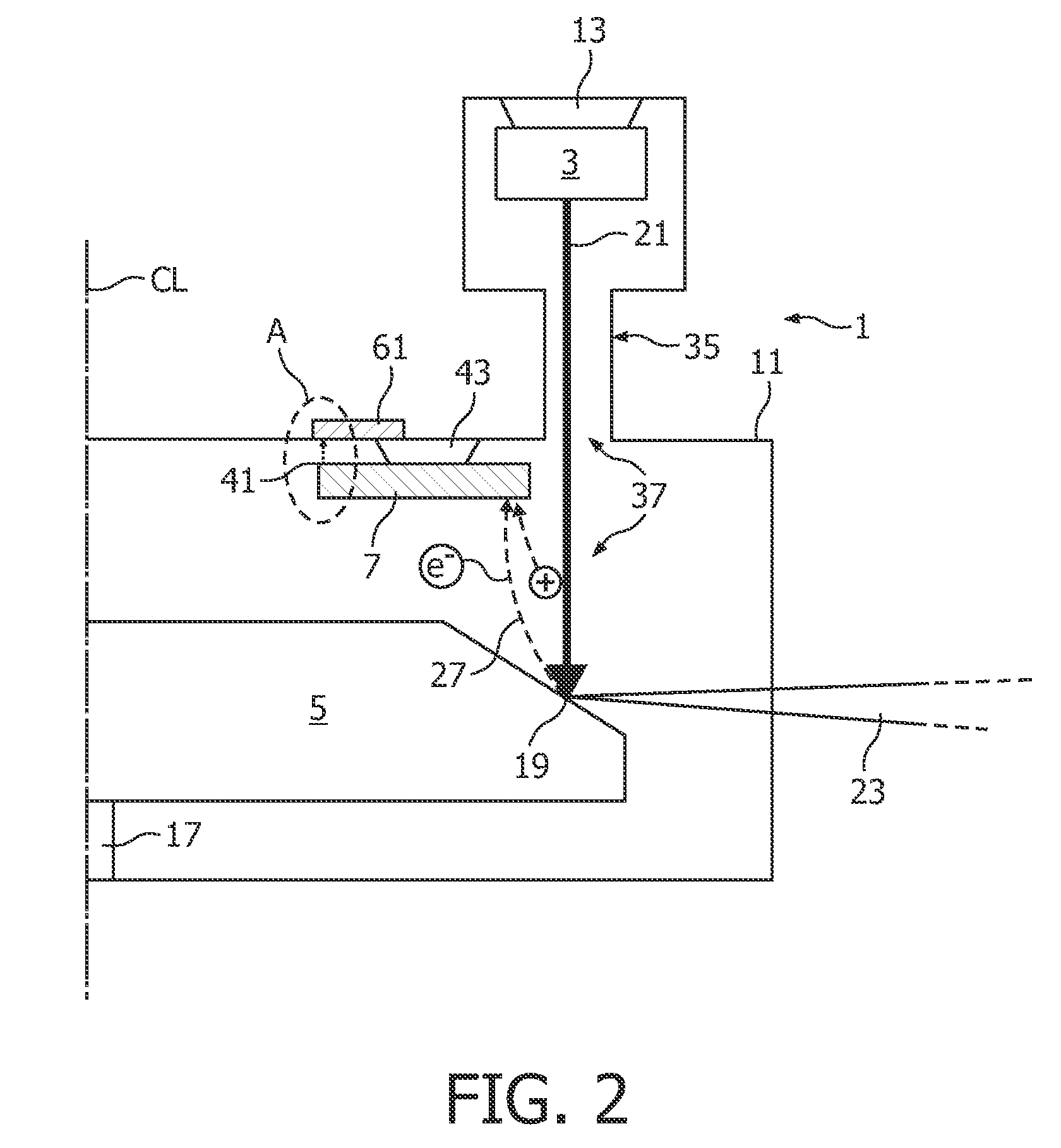
[0041]FIG. 1 shows a conventional X-ray tube 101 comprising as main components a cathode 103 and an anode 105. The components of the X-ray tube 101 are enclosed by a housing 111. The cathode 103 is set to a highly negative potential of for example −120 kV and is mechanically attached to the housing 111 by an electrically insulating element 113 such that the cathode 103 is electrically isolated against the housing 111. The anode 105 is designed as round disk which can be rotated around a rotation axis 117. The anode 105 comprises a slanted surface 115. Electrons (e−) of a primary electron beam 121 emitted from the cathode 103 and accelerated towards the anode 105 impact onto the anode 105 in a focal point 119 on the slanted surface 115.

[0042]Upon such impact of electrons, a portion of approximately 60% of the electron beam 121 directed onto the anode 105 serves for generating a beam of X-rays 123. This beam of X-rays 123 can be transmitted through a window 125 within the housing 111 ...


PUM


Abstract

An X-ray tube (1) comprising a cathode (3), an anode (5) and a further electrode (7) is proposed. Therein, the further electrode is arranged and adapted such that, due to impact of ‘free electrons (27) coming from the anode (5), the further electrode (7) negatively charges to an electrical potential lying between a cathode's potential and an anode's potential. The further electrode (7) may be passive, i.e. substantially electrically isolated and not connected to an active external voltage supply. The further electrode (7) may act as an ion pump removing ions from within a primary electron beam (21) and furthermore also removing atoms of residual gas within the housing (11) of the X-ray tube (1). In order to further increase the ion pumping capability of the further electrode (7), a magnetic field generator (61) can be arranged adjacent to the further electrode (7).

Description

FIELD OF THE INVENTION[0001]The present invention relates to an X-ray tube with an ion collecting electrode which X-ray tube may for example be used in computer tomography (CT) systems.BACKGROUND OF THE INVENTION[0002]X-ray tubes are for example used in CT systems wherein the X-ray tube is rotating about a patient, generating a fan-beam of X-rays, wherein opposite to the X-ray tube and with it on a gantry rotor rotates a detector system which converts the attenuated X-rays into electrical signals. Based on these electrical signals, a computer system may reconstruct an image of the patient's body.[0003]In the X-ray tube, a beam of primary electrons emitted from a cathode hits a focal spot of an anode and creates X-rays. However, a percentage of the incoming primary electrons is backscattered or creates recoil electrons, these electrons being hereinafter commonly referred to as back-directed electrons. Thereby, it is converted to a current of back-directed electrons leaving the focal ...

Claims


Application Information

Patent Timeline
Patent Type & Authority Applications(United States)
IPC IPC(8): H01J35/16B82Y99/00
CPCH01J35/16H01J2235/205H01J2235/168
Inventor BEHLING, ROLF KARL OTTOHAUTTMANN, STEFAN
Owner KONINKLIJKE PHILIPS ELECTRONICS NV
Why Eureka
Try Eureka