
Film deposition apparatus, film deposition method, and computer readable storage medium

Inactive Publication Date: 2011-02-17
TOKYO ELECTRON LTD
View PDF22 Cites 57 Cited by
  • Summary
  • Abstract
  • Description
  • Claims
  • Application Information

AI Technical Summary

Benefits of technology

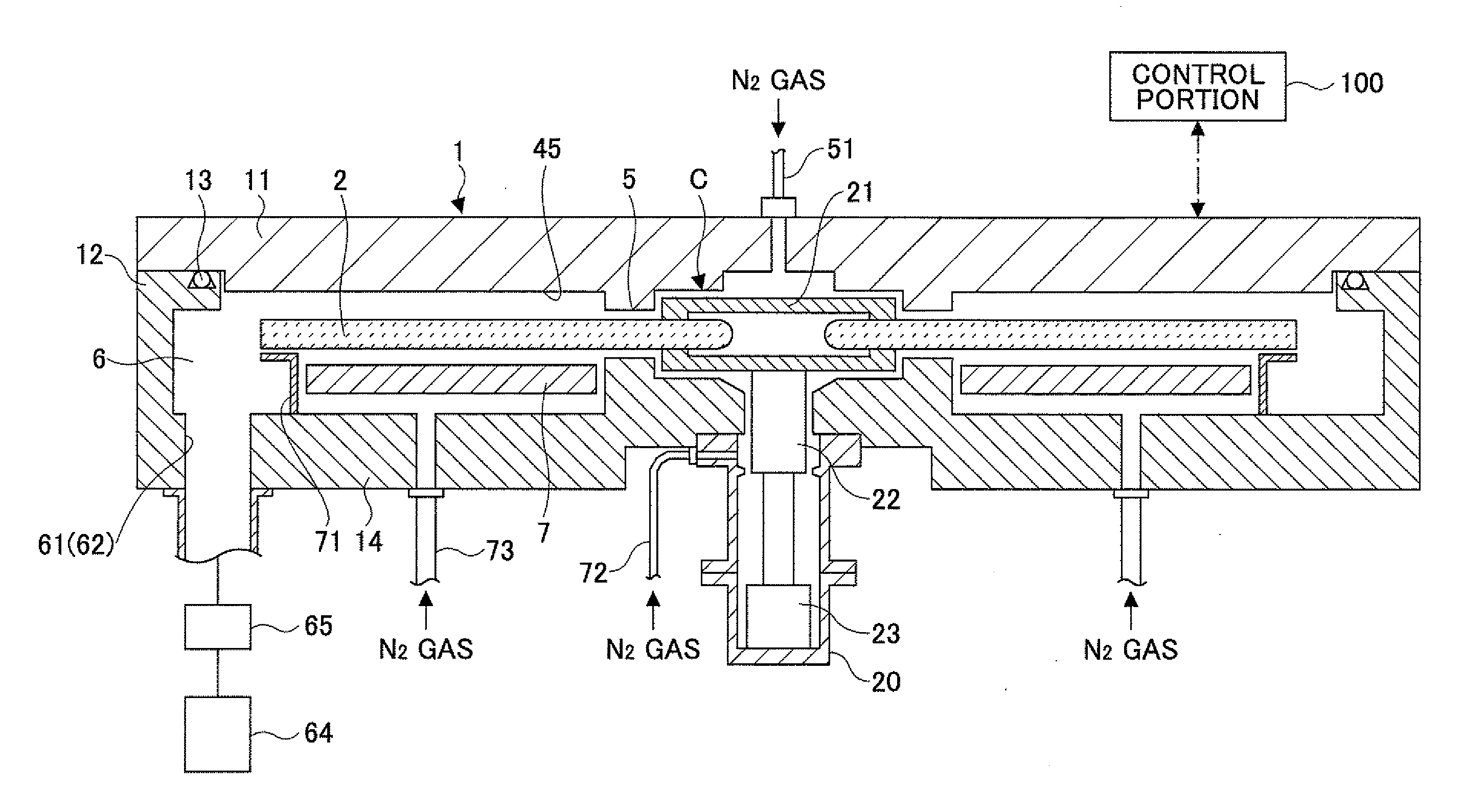
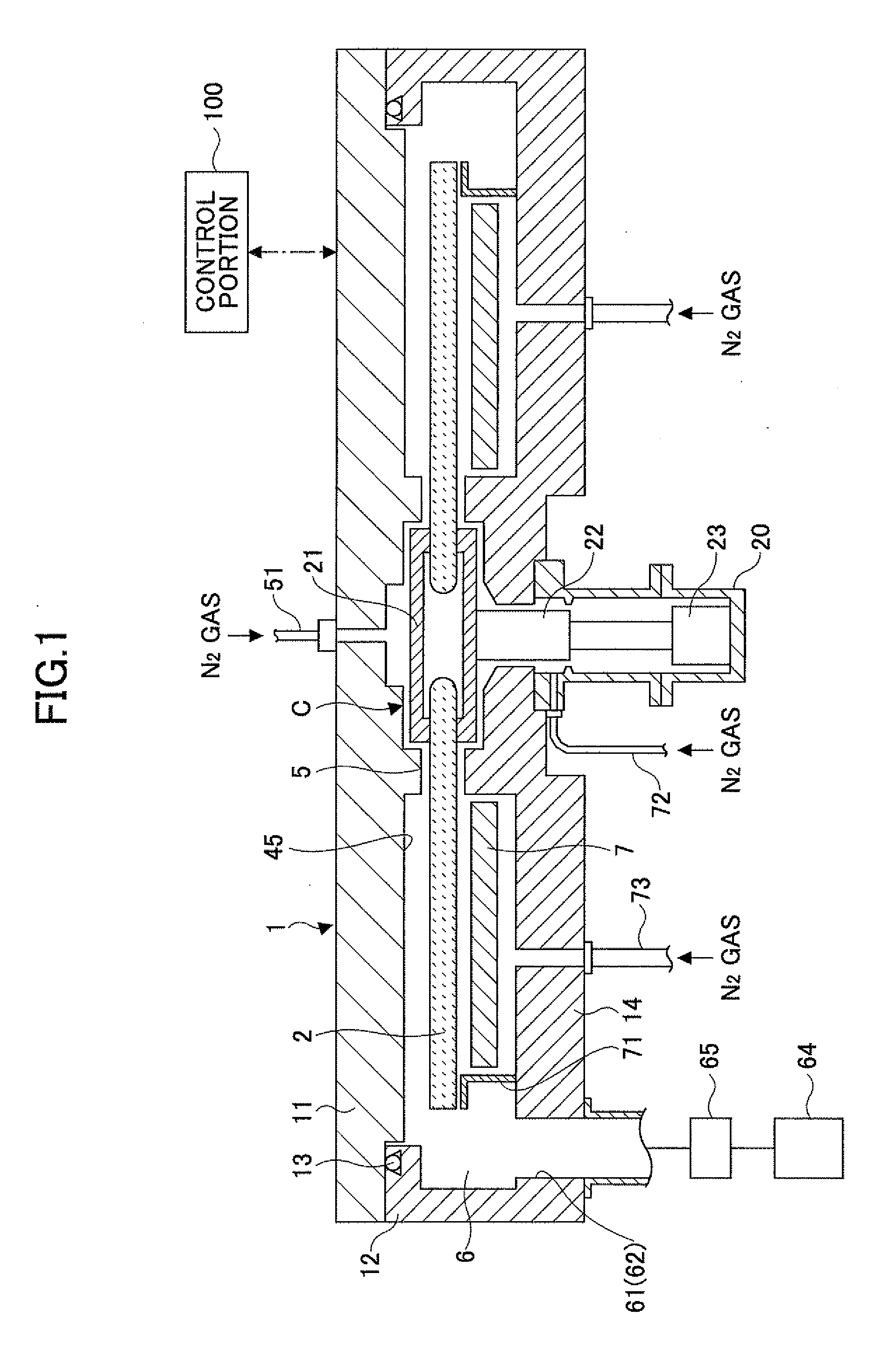
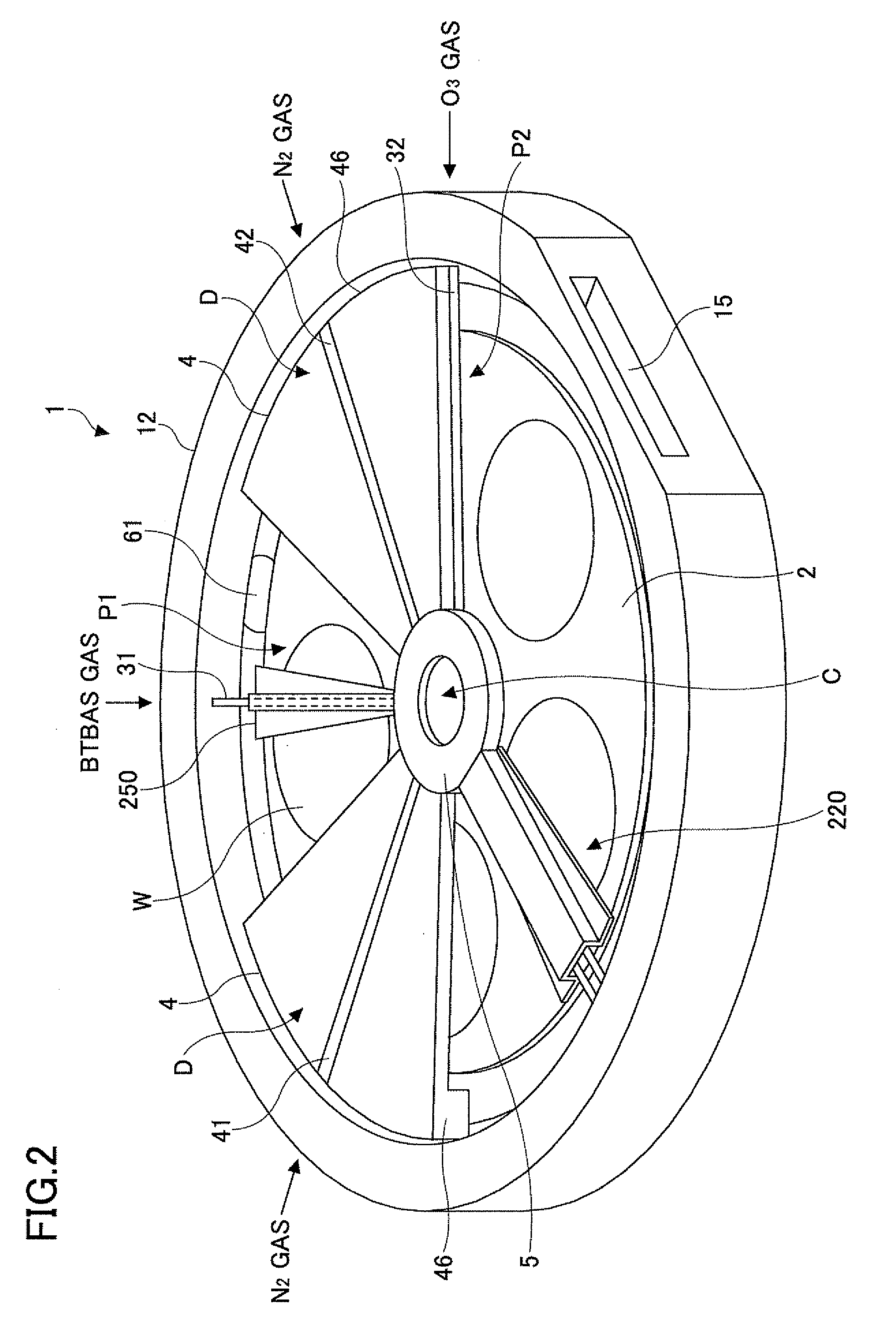
[0010]The present invention has been made in view of the above, and provides a film deposition apparatus and a film deposition method for depositing a film on a substrate by carrying out plural cycles of supplying in turn at least two source gases to the substrate in order to form plural layers of a reaction product, which can provide a consolidated thin film with few impurities and having a uniform film thickness and film property, and a computer readable storage medium for causing the film deposition apparatus to execute the film deposition method.

Problems solved by technology

However, performing such subsequent process on plural layers of thin films increases the number of steps and increases cost.
This may prevent the subsequent process from being uniformly performed on the surface of the wafer.
In such a case, the film thickness and the film property of the thin film may become inconsistent.

Method used


Image

  • Film deposition apparatus, film deposition method, and computer readable storage medium
  • Film deposition apparatus, film deposition method, and computer readable storage medium
  • Film deposition apparatus, film deposition method, and computer readable storage medium

Examples


experiment 1

Wet Etching Rate

[0123]An experiment was performed to confirm the uniformity of resistance against wet etching in an in-plane direction of the wafer W in a case of performing a reforming process on a silicon oxide film every deposition cycle (l rotation of the turntable 2) where Ar gas is used together with O2 gas as the process gas for generating plasma. Because impurities are eliminated from the silicon oxide film by the reforming process, the purity of the silicon oxide wafer is improved and the resistance against wet etching is improved. Thus, this experiment confirmed how much the reforming process was performed by measuring the wet etching rate.

[0124]After the silicon oxide film is deposited by the following conditions, a wafer W is steeped in a hydrofluoric acid resolution and then the film thickness of the silicon oxide film is measured, to thereby calculate the wet etching rate. The film thickness of the silicon oxide film was measured in plural areas of the wafer W along a ...

experiment 2

Wet Etching Rate

[0127]Next, in a similar manner as Experiment 1, an experiment was performed to confirm the uniformity of deposition rate in an in-plane direction of the wafer W in a case where Ar gas is used together with O2 gas as the process gas for generating plasma. That is, because impurities are eliminated from the silicon oxide film by the reforming process and the silicon oxide film shrinks, this experiment confirmed the uniformity of the reforming process by measuring the deposition rate. The experiment calculates the film deposition rate by measuring the film thickness from the center to the outer circumference of the turntable 2.

(EXPERIMENT CONDITIONS)HIGHPROCESS GAS FORFREQUENCYGENERATING PLASMA ANDFOR REFORMGAS FLOW RATE (slm)PROCESSREFERENCEArO2YESEXAMPLE 250  EMBODIMENTArO22-150.1EMBODIMENTArO22-2  4.50.5

[0128]In the experiment, diisopropyl amine silane gas having less vapor pressure than the above-described BTBAS gas, having less molecules and having organic materia...

experiment 3

Scattering of Film Deposition Rate

[0130]Next, an experiment similar to that of Experiment 2 is performed and then scattering of the film deposition rate is calculated based on the average value of the film deposition rate obtained in the in-plane direction of the wafer W. In this case, the flow rate of the first reaction gas is 275 sccm; the film deposition temperature is 350° C.; the process pressure is 1.07 kPa (8 Torr); and the rotational speed of the turntable 2 is 240 rpm. Other process conditions and the position of measuring the film deposition rate are the same as Experiment 2. As a result, similar to Experiment 2, the scattering of the film deposition rate is reduced as illustrated in FIG. 22 by using Ar gas together with O2 gas as the process gas for generating plasma.


PUM

PropertyMeasurementUnit
Areaaaaaaaaaaa

Abstract

A silicon oxide film is deposited by rotating a rotation table on which a wafer W is placed to allow BTBAS gas to be adsorbed on an upper surface of the wafer W and supply a O3 gas to the upper surface of the wafer W for allowing the BTBAS gas adsorbed on the upper surface of the wafer W to react. After depositing the silicon oxide film, a reforming process is performed every deposition cycle by supplying a plasma of Ar gas to the silicon oxide film on the wafer from an activated gas injector.

Description

CROSS-REFERENCE TO RELATED APPLICATION[0001]This application claims the benefit of priority of Japanese Patent Application No. 2009-186709, filed on Aug. 11, 2009 with the Japanese Patent Office, the entire content of which is hereby incorporated by reference.BACKGROUND OF THE INVENTION[0002]1. Field of the Invention[0003]The present invention relates to a film deposition apparatus and a film deposition method for depositing a film on a substrate by carrying out plural cycles of supplying in turn at least two source gases to the substrate in order to form plural layers of a reaction product, and a storage medium storing a computer program for carrying out the film deposition method.[0004]2. Description of the Related Art[0005]As a film deposition technique in a semiconductor fabrication process, there has been known a process, in which a first reaction gas is adsorbed on a surface of a semiconductor wafer (referred to as a wafer hereinafter) and the like under vacuum and then a seco...

Claims


Application Information

Patent Timeline
IPC IPC(8): C23C14/22C23C16/44
CPCC23C16/402C23C16/45551C23C16/45536
Inventor KATO, HITOSHIKIKUCHI, HIROYUKIUSHIKUBO, SHIGEHIRO
Owner TOKYO ELECTRON LTD
Learn More