Film forming apparatus and film forming method

Inactive Publication Date: 2011-02-17
TOKYO ELECTRON LTD
View PDF3 Cites 39 Cited by
  • Summary
  • Abstract
  • Description
  • Claims
  • Application Information

AI Technical Summary

Benefits of technology

[0018]As described above, according to the present invention, the formation of an organic film on a wall surface of a film forming container may be suppressed by suppressing a thermal polymerization reaction on the wall surf

Problems solved by technology

However, since the conventional method uses the solvent, impurity introduction or the like occurs and it is difficult to obtain a thin film having a uniform thickness less than 1000 Å. Also, as a method for obtaining a monomolecular layer film, manufacture of a thin film using a Langmuir-Blodgett (LB) method has been studied.
However, since reactions, such as substitution of hydrophilic and hydrophobic groups and the like, are complicated and, it is difficult to control a surface pressure required when the thin film is obtained,

Method used


Image

  • Film forming apparatus and film forming method
  • Film forming apparatus and film forming method
  • Film forming apparatus and film forming method

Examples


Example

Embodiment 1

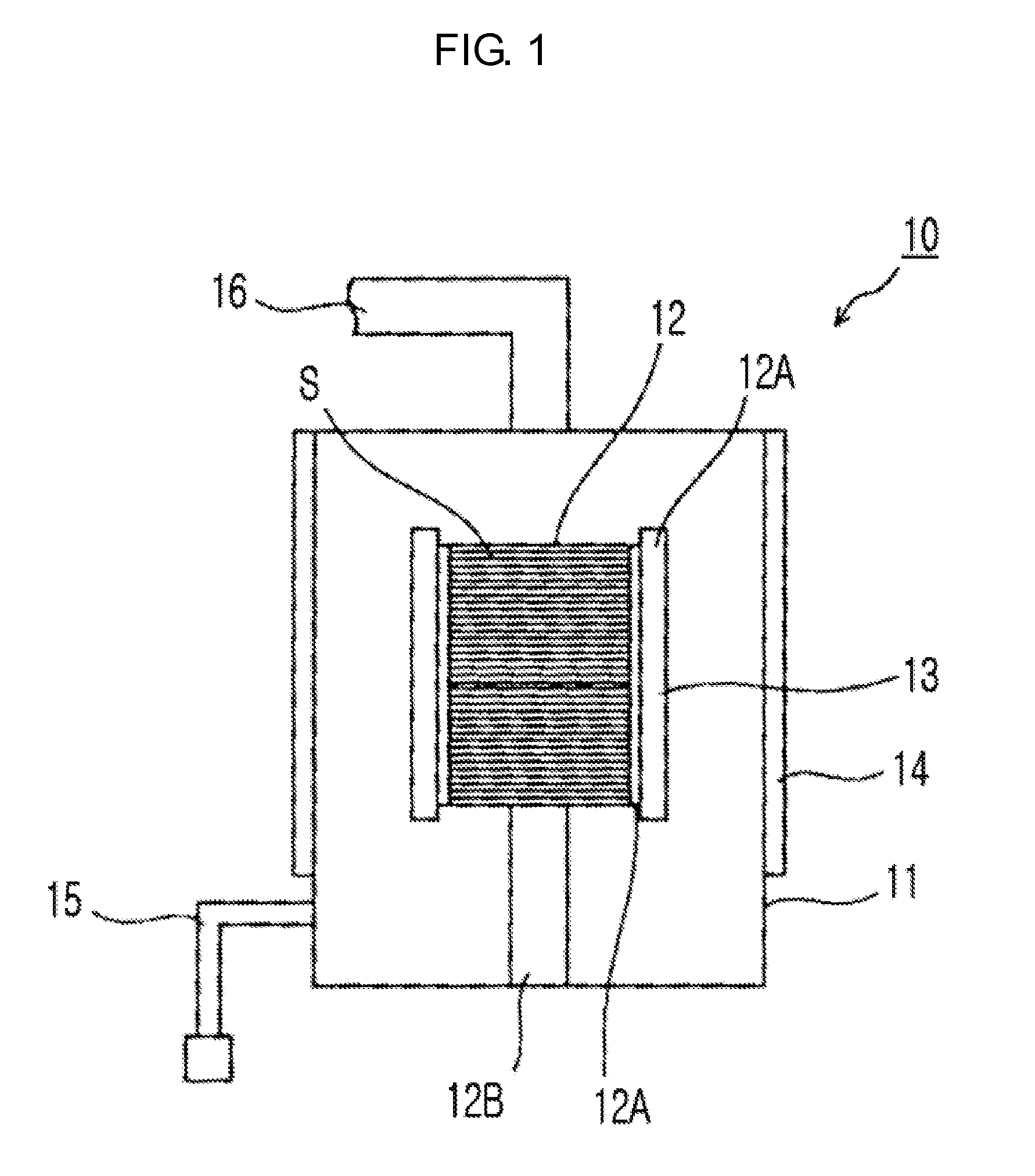
[0027]FIG. 1 is a view schematically showing an example of a configuration of a film forming apparatus according to the present invention.

[0028]In a film forming apparatus 10 shown in FIG. 1, a boat 12 is received as a substrate-supporting container in a film forming container 11, and is fixed to a bottom surface of the film forming container 11 by a support member 12B formed at a lower portion of the film forming container 11. Also, a support member 12A protrudes in a horizontal direction from upper and lower ends of the boat 12, and an internal heater 13 is formed to be engaged to the support member 12A. Also, an external heater 14 is formed along a wall surface of an outer wall of the film forming container 11. Also, a supply pipe 15 of a material monomer is formed at the lower portion of the film forming container 11.

[0029]Also, an exhaust pipe 16, which is connected to an exhaust system (not shown) and through which the film forming container 11 is exhausted to a de...

Example

Embodiment 2

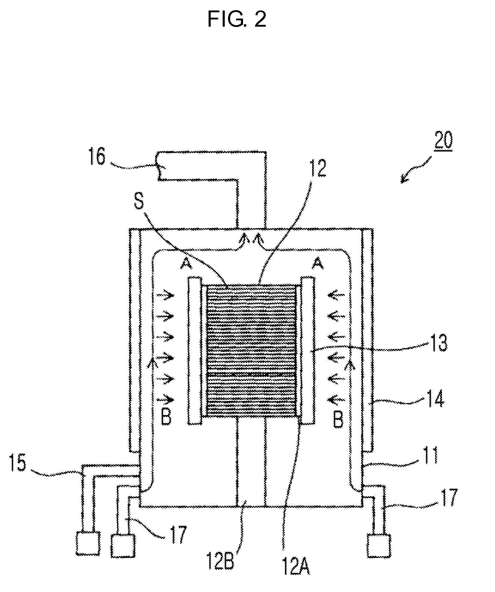
[0041]FIG. 2 is a view schematically showing another example of a configuration of a film forming apparatus according to the present invention. Also, the same or similar elements as or to those of the film forming apparatus 10 shown in FIG. 1 will be denoted by the same reference numerals.

[0042]In a film forming apparatus 20 shown in FIG. 2, the boat 12 is received as a substrate-supporting container in the film forming container 11, and is fixed to a bottom surface of the film forming container 11 by the support member 12B formed at a lower portion of the film forming container 11. Also, the support member 12A protrudes in a horizontal direction from upper and lower ends of the boat 12, and the internal heater 13 is formed to be engaged to the support member 12A. Also, the external heater 14 is formed along a wall surface of an outer wall of the film forming container 11. Also, the supply pipe 15 of a material monomer and a supply pipe 17 of a heating gas are formed at ...

Example

Embodiment 3

[0050]FIG. 3 is a view schematically showing yet another example of a configuration of a film forming apparatus according to the present invention. FIG. 4 is a view schematically showing a configuration of a gas introduction pipe used in the film forming apparatus shown in FIG. 3. Also, the same or similar elements as or to those of the film forming apparatus 10 shown in FIG. 1 are denoted by the same reference numerals.

[0051]In a film forming apparatus 30 shown in FIG. 3, the boat 12 is received as a substrate-supporting container in the film forming container 11, and is fixed to a bottom surface of the film forming container 11 by the support member 12B formed at a lower portion of the film forming container 11. Also, the support member 12A protrudes in a horizontal direction from upper and lower ends of the boat 12, and the internal heater 13 is formed to be engaged to the support member 12A. Also, the external heater 14 is formed along a wall surface of an outer wall...


PUM

PropertyMeasurementUnit
Temperatureaaaaaaaaaa
Boiling pointaaaaaaaaaa
aaaaaaaaaa

Abstract

A wall surface of a film forming container is heated to or above a vaporization temperature of a material monomer, which is used to form an organic film, by using an external heater formed along the wall surface of the film forming container, substrates are heated to a thermal polymerization reaction temperature by using an internal heater that is disposed apart from the external heater and near a substrate-supporting container in which the substrates are received, and the organic film is formed through thermal polymerization occurring on the substrates by supplying the material monomer into the film forming container.

Description

TECHNICAL FIELD[0001]The present invention relates to a film forming apparatus and a film forming method, and more particularly, to a film forming apparatus and a film forming method suitable for forming of an organic film through a thermal polymerization reaction.BACKGROUND ART[0002]A polymer organic film may be used as an interlayer insulating film of LSI or the like or a liquid crystal alignment film, and has very excellent electrical, optical, and mechanical characteristics. In particular, since, for example, polyimide or the like has a high glass transition point and has excellent heat resistance, chemical stability, alignment control, and the like, polyimide or the like is used as a heat- and radiation-resistant material and a space-survival material, and is also being considered to be used as an insulating material of a superconducting magnet used in a fusion reactor, a protective material for preventing degradation of a material for machinery due to atomic oxygen in space, o...

Claims


Application Information

Patent Timeline
IPC IPC(8): H01L21/47C23C16/00C23C16/44C23C16/46
CPCB05D1/60B05D3/0473B05D3/0493H01L21/312C23C14/243H01L21/02126H01L21/02312C23C14/12
Inventor NAKAO, KENHARADA, MUNEO
Owner TOKYO ELECTRON LTD
Why Eureka
Try Eureka