
Carbon Dioxide Capture/Regeneration Structures and Techniques

a carbon dioxide and structure technology, applied in the field of carbon dioxide capture/regeneration structures and techniques, can solve the problems of generating negative carbon, 300/b> times more expensive, and using ambient air as opposed to flue gas

Active Publication Date: 2011-02-24
GLOBAL THERMOSTAT OPERATIONS LLC
View PDF86 Cites 45 Cited by
  • Summary
  • Abstract
  • Description
  • Claims
  • Application Information

AI Technical Summary

Benefits of technology

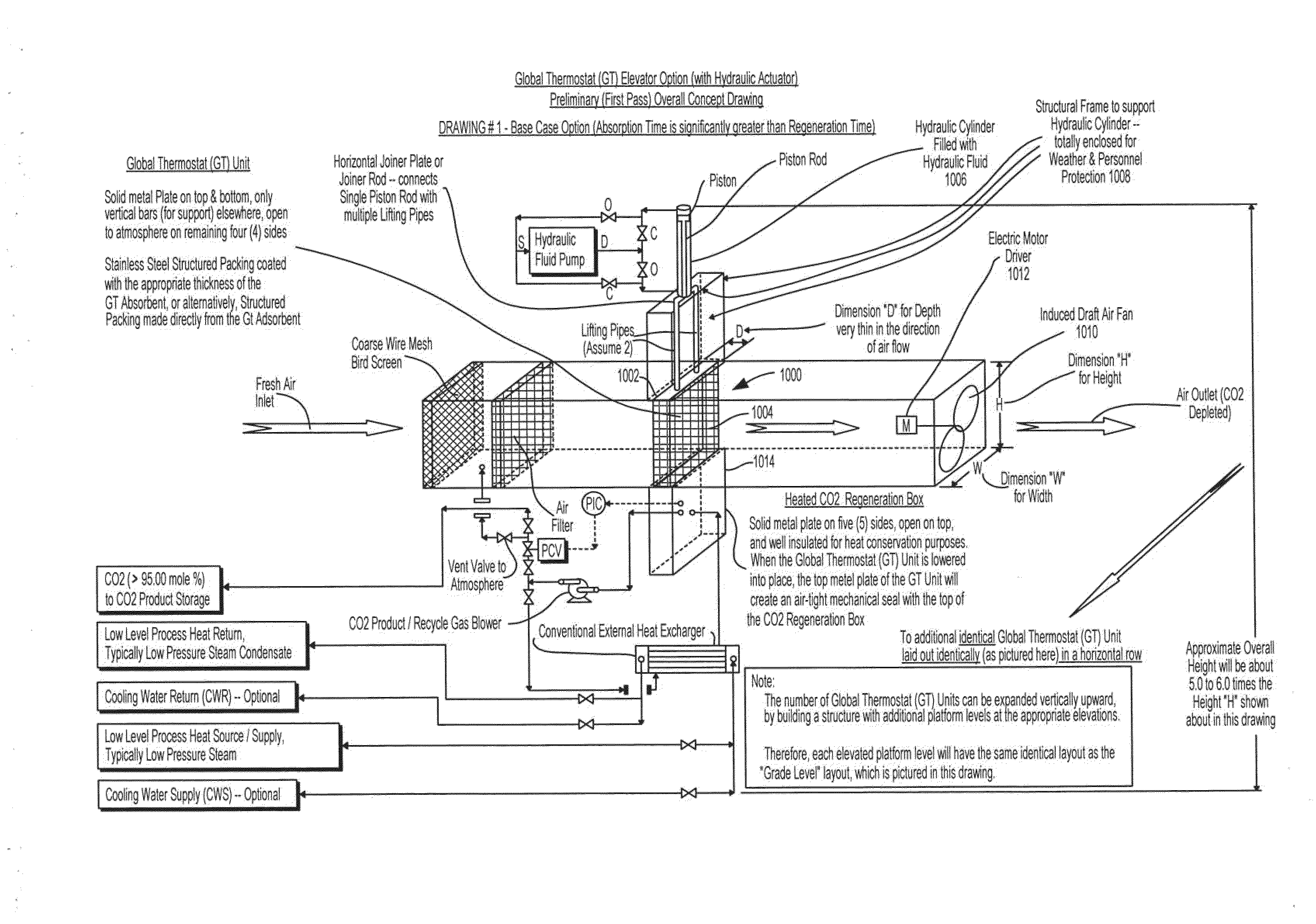
[0014]In one of its basic aspects, this application provides additional structures and techniques for separating carbon dioxide from carbon dioxide laden air, and using process heat to separate carbon dioxide from a sorbent and regenerate the sorbent that further improves the system disclosed in application Ser. No. 12 / 124,864, and particularly FIG. 6 of that application.

Problems solved by technology

In the former case it goes directly against conventional wisdom that 300 times lower concentration of the CO2 in ambient atmosphere would expect it to be 300 times more expensive since separation costs are thought to generally scale inversely with the concentration.
Thus federally funded efforts have been directed at extracting CO2 from the flue gas emissions of power plants (e.g. clean coal) and experts have publicly claimed that the use of ambient air as opposed to flue gas makes no sense.
In addition, the applicants' approach would produce negative carbon, actually reducing the amount of CO2 in the atmosphere, while cleaning up the flue gas would only prevent the CO2 content in the air from increasing.
Further analysis shows that one cannot solve the global warming problem in a timely manner to reduce the great risk it poses by simply cleaning up large stationary fossil fuel sources like coal plants or for that matter by conservation or use of renewables.
Other published schemes for extracting CO2 from the ambient atmosphere have used higher temperature heat generally and not process heat specifically and therefore have not been seriously considered because of their high energy costs.
However, because at this time this heat is much less available, and more costly, its use could limit the full scope of this invention to the effect that it might not adequately address climate change, and the use of NAOH as a sorbent is therefore not preferred at this time.
During the past history of our planet, for example, there have been many periods of glaciation and rapid temperature swings that have caused destruction and even mass extinctions.
Such temperature swings in the future could be a direct cause of massive damage and destabilization of human society from conflicts resulting from potential diminished resources.
Thus the LP steam receives all the steam that cannot be used usefully at the higher steam levels.
However, as the steam is reduced in pressure by passing through the turbines energy is generated and this reduces the cost of the steam.
In addition it is much more likely that there will not be an adequate supply of 60 psig available and that additional VHP steam would have to be generated.
This would raise the cost of the 60 psig steam as it would either have to be charged at the full cost of VHP steam or additional turbines would have to be installed to recover power, but this would involve significant capital costs.

Method used


Image

  • Carbon Dioxide Capture/Regeneration Structures and Techniques
  • Carbon Dioxide Capture/Regeneration Structures and Techniques
  • Carbon Dioxide Capture/Regeneration Structures and Techniques

Examples


Embodiment Construction

Background Description of the System and Method Concepts of application Ser. No. 12 / 124,864

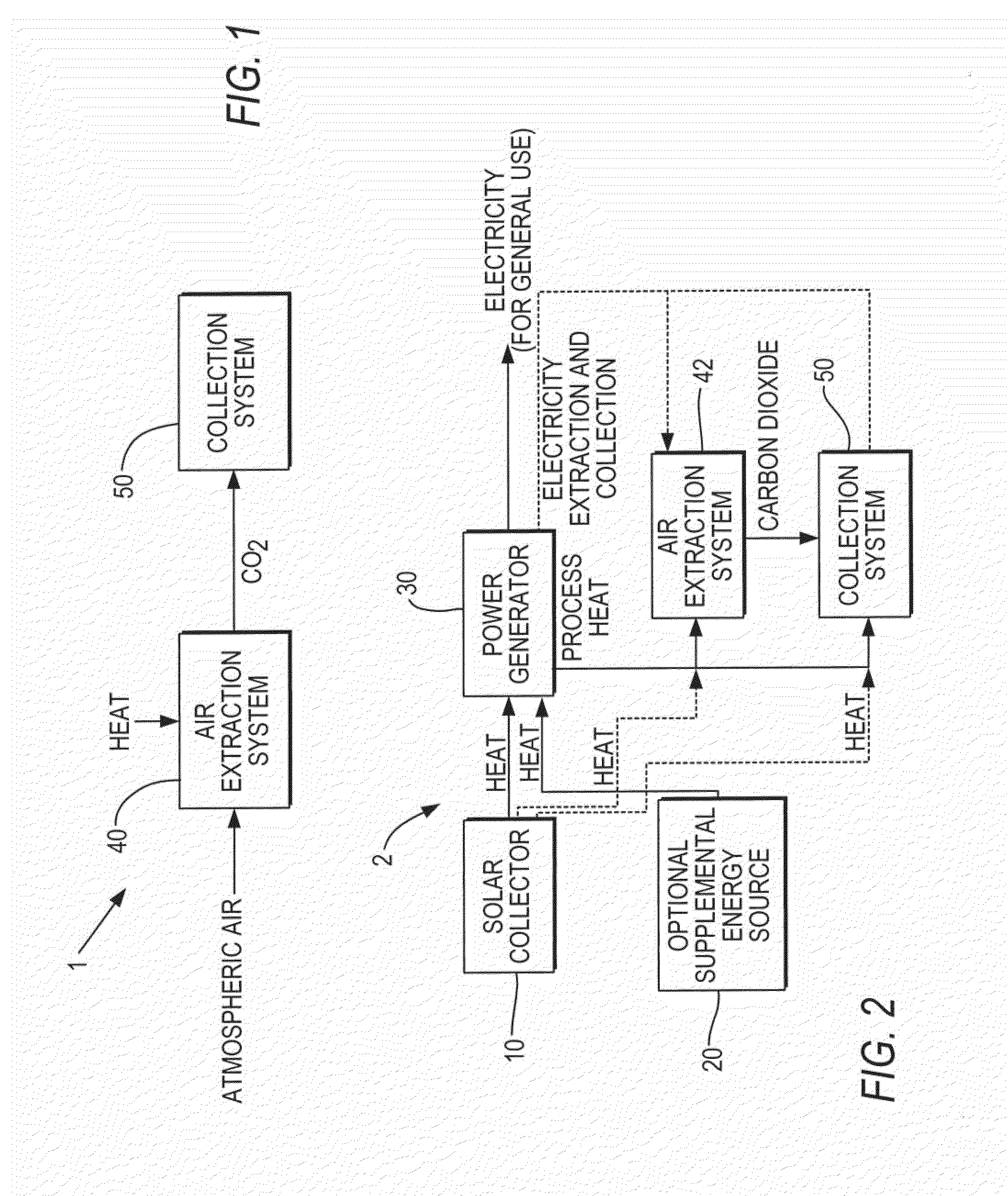
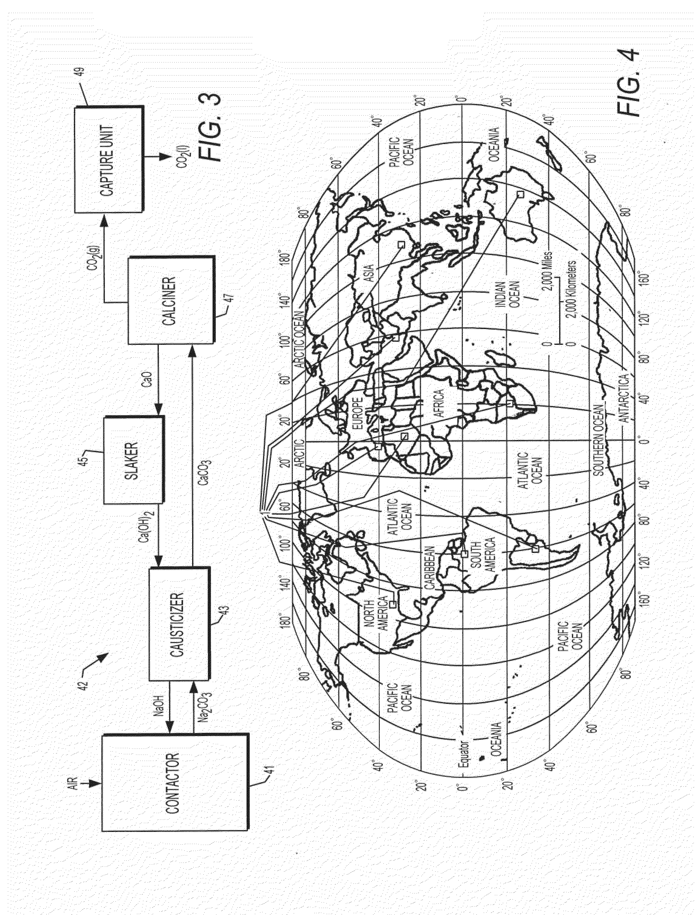
[0036]Initially, it is believed useful to describe the method and system of U.S. application Ser. No. 12 / 124,864, to provide background for the additional ways the present invention further develops those principles. FIGS. 1-9 illustrate the system and method of application Ser. No. 12 / 124,864. FIG. 1 is a generalized block diagram of a system, generally designated by reference number 1, for removing carbon dioxide from an atmosphere according to an exemplary embodiment of the present invention. The system 1 includes an air extraction system 40 and a collection system 50 that isolates the removed carbon dioxide to a location for at least one of sequestration, storage and generation of a renewable carbon fuel or the generation of a non-fuel product such as fertilizer and construction materials (or to be used in green houses or to enhance the rate of microbial production of biofuels). The air ex...


PUM

PropertyMeasurementUnit
massaaaaaaaaaa
concentrationaaaaaaaaaa
energyaaaaaaaaaa

Abstract

New and useful system and method concepts are provided, for removing carbon dioxide from a flow of carbon dioxide laden air. More specifically, a sorbent structure is used in new and useful structures and techniques to bind carbon dioxide in a carbon dioxide laden air stream, and process heat is used to separate carbon dioxide from the sorbent structure and regenerate the sorbent structure.

Description

[0001]This application claims the benefit of priority pursuant to 35 U.S.C. 119(e) from a U.S. provisional patent application having Application No. 61 / 210,296 filed Mar. 17, 2009.RELATED APPLICATION / CLAIM OF PRIORITY[0002]The present invention relates to systems and methods for removing greenhouse gases from an atmosphere, and in particular to systems and methods for removing carbon dioxide from an atmosphere. In addition, the present invention is a continuation in part of, and further develops concepts disclosed in application Ser. No. 12 / 124,864, filed May 21, 2008, and entitled System and Method for Removing Carbon Dioxide from an Atmosphere and Global Thermostat Using the Same; which is a continuation-in-part of a U.S. patent application Ser. No. 11 / 825,468 (Attorney Docket No. 6236.104US), filed on Jul. 6, 2007, which in turn is a continuation-in-part of U.S. patent application Ser. No. 11 / 805,477 (Attorney Docket No. 6236.103US), filed on May 22, 2007, which in turn is a cont...

Claims


Application Information

Patent Timeline
Patent Type & Authority Applications(United States)
IPC IPC(8): B01D53/62B01D53/14B01D53/18C01B32/50
CPCB01D53/1475B01D53/62B01D53/83B01D2257/504F23J15/02F23J2215/50B01D53/08F23J2219/50F23J2219/60Y02C10/04Y02C10/06Y02C10/08F23J2219/40B01D2256/22Y02P20/133Y02E20/32Y02C20/40B01D53/005B01D53/02B01D53/04B01D53/14B01D53/1456
Inventor EISENBERGER, PETER
Owner GLOBAL THERMOSTAT OPERATIONS LLC
Learn More