Coreless packaging substrate and method for fabricating the same

a technology of packaging substrates and cores, which is applied in the manufacture of printed circuits, printed circuit aspects, metallic pattern materials, etc., can solve the problems of increasing the length of wires and thickness of the overall structure of the core board, poor coplanarity of solder bumps, and difficult control, so as to reduce the length of wires and thickness of the overall structure. , the effect of low height variation and efficient control of average value and deviation

Active Publication Date: 2011-02-24
UNIMICRON TECH CORP
View PDF5 Cites 21 Cited by
  • Summary
  • Abstract
  • Description
  • Claims
  • Application Information

AI Technical Summary

Benefits of technology

[0023]Therefore, the present invention forms small aperture openings in the auxiliary dielectric layer and the first resist layer so as to efficiently control the average value and deviation of the volume and height of the conductive bumps formed in the openings, thereby achieving ultra-fine pitch bumps.
[0024]In particular, the conductive bumps of the present invention comprise the metal pillars w...

Problems solved by technology

However, the use of the core board increases the length of wires and thickness of the overall structure.
The etch-induced diameter and depth deviations make it difficult to control the volume and height deviation of the solder bumps 141a to be formed subsequently in the concave portions 130, thus leading to poor coplanari...

Method used


Image

  • Coreless packaging substrate and method for fabricating the same
  • Coreless packaging substrate and method for fabricating the same
  • Coreless packaging substrate and method for fabricating the same

Examples


Embodiment Construction

[0027]The following illustrative embodiments are provided to illustrate the disclosure of the present invention, these and other advantages and effects can be apparent to those in the art after reading this specification.

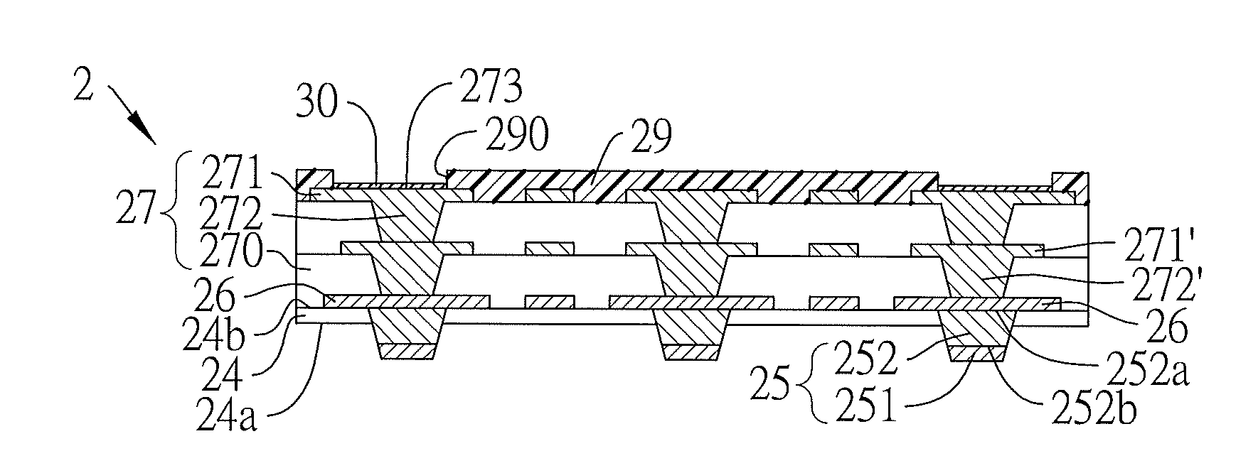
[0028]FIGS. 2A to 2K are sectional views showing a coreless packaging substrate and a method for fabricating the same according to the present invention.

[0029]Referring to FIG. 2A, a base material 2a is provided, which comprises a carrier layer 20 having two opposing surfaces, a release film 21 formed on portions of the two opposing surfaces of the carrier layer 20, an adhesive layer 20a formed on the two opposing surfaces of the carrier layer 20 outside the release film 21, a metal layer 22 formed on the release film 21 and the adhesive layer 20a, a first resist layer 23a formed on the metal layer 22, and an auxiliary dielectric layer 24 formed on the first resist layer 23a, wherein an active region A is defined on the auxiliary dielectric layer 24, the carrier lay...


PUM


Abstract

A coreless packaging substrate includes: a substrate body including an auxiliary dielectric layer having opposing first and second surfaces, an inner wiring formed on the second surface, and a built-up structure formed on both the second surface of the auxiliary dielectric layer and the inner wiring; and a plurality of conductive bumps including metal pillars having opposing first and second ends and a solder layer formed on the first end, wherein the second ends of the metal pillars are disposed in the auxiliary dielectric layer and electrically connecting with the inner wiring, and the first ends of the metal pillars with the solder layer protrude from the first surface of the auxiliary dielectric layer, thereby achieving ultra-fine pitch and even-height conductive bumps. A method for fabricating the coreless packaging substrate as described above is further provided.

Description

BACKGROUND OF THE INVENTION[0001]1. Field of the Invention[0002]The present invention relates generally to coreless packaging substrates and methods for fabricating the same, and more particularly, to a coreless, ultra-fine pitch packaging substrate and a method for fabricating the same.[0003]2. Description of Related Art[0004]Along with the development of electronic industries, electronic products have a trend towards miniaturization and high performance, and accordingly multi-layer boards are developed so as to increase the layout area for the layout through interlayer connection techniques, and meet demands for high-density integrated circuits and meanwhile reduce the thickness of packaging substrates.[0005]Conventionally, a multi-layer board comprises a core board and built-up structures disposed on two sides of the core board. However, the use of the core board increases the length of wires and thickness of the overall structure. Accordingly, coreless boards are developed to ov...

Claims


Application Information

Patent Timeline
IPC IPC(8): H05K1/09H01L21/768H05K1/11
CPCH05K3/205H05K3/3473H05K3/4007H05K3/4682H05K2201/0355Y10T29/49147H05K2201/10984H01L2924/0002H05K2201/0367H01L2924/00
Inventor HSU, SHIH- PING
Owner UNIMICRON TECH CORP
Why Eureka
Try Eureka