Multi-Leaf Collimators

a collimator and leaf technology, applied in the direction of electrodes and associated parts, radiation therapy, therapy, etc., can solve the problems of dynamic radiation delivery discontinuities, achieve continuous and smooth treatment delivery, increase the available leaf speed, and accelerate the effect of dose ra

Active Publication Date: 2011-03-03
ELEKTA AB
View PDF2 Cites 18 Cited by
  • Summary
  • Abstract
  • Description
  • Claims
  • Application Information

AI Technical Summary

Benefits of technology

[0012]When delivering a true dynamic or VMAT delivery treatment, the treatment time is directly related to the speed at which the continuous (linearly interpolated) collimating shapes are made. The available speed of all axes (including the leaves) are used to calculate the actual dose rate used within the treatment to ensure a continuous and smooth treatment delivery. Increasing the available leaf speed allows potential selection of a faster dose rate in those instances where leaf motion is the limiting factor.
[0013]Previous efforts have therefore been directed to increasing the maximum speed of travel of the leaves, and to extending the maximum length of leaves so that carriage movement during delivery is less likely to be required.
[0014]Most MLCs have a means for sensing the current positions of the leaves relative to the substrate, such...

Problems solved by technology

As a result, discontinuities arise during dynamic radiation delivery if the carriage has to be rep...

Method used


Image

  • Multi-Leaf Collimators
  • Multi-Leaf Collimators

Examples


Embodiment Construction

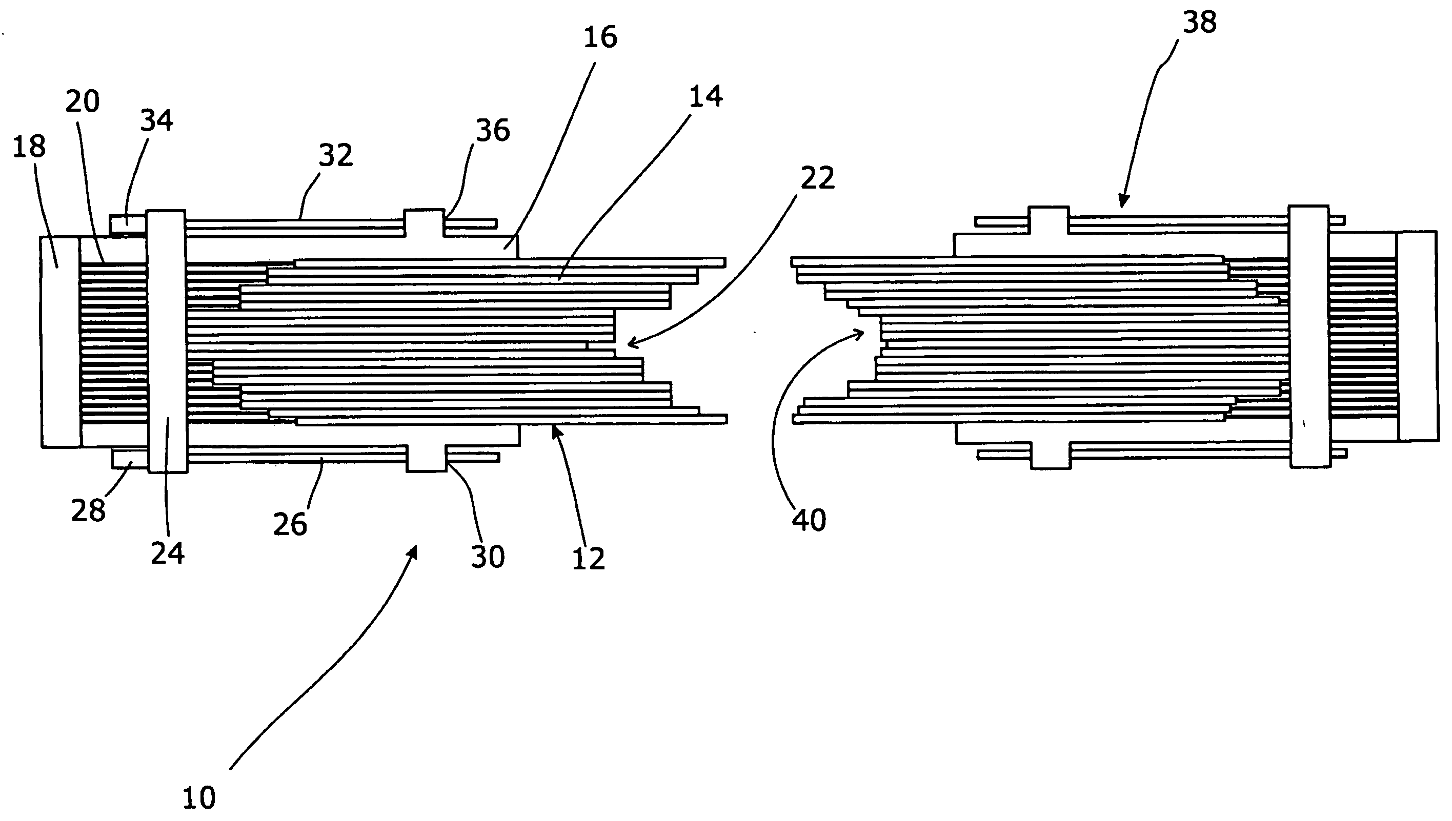
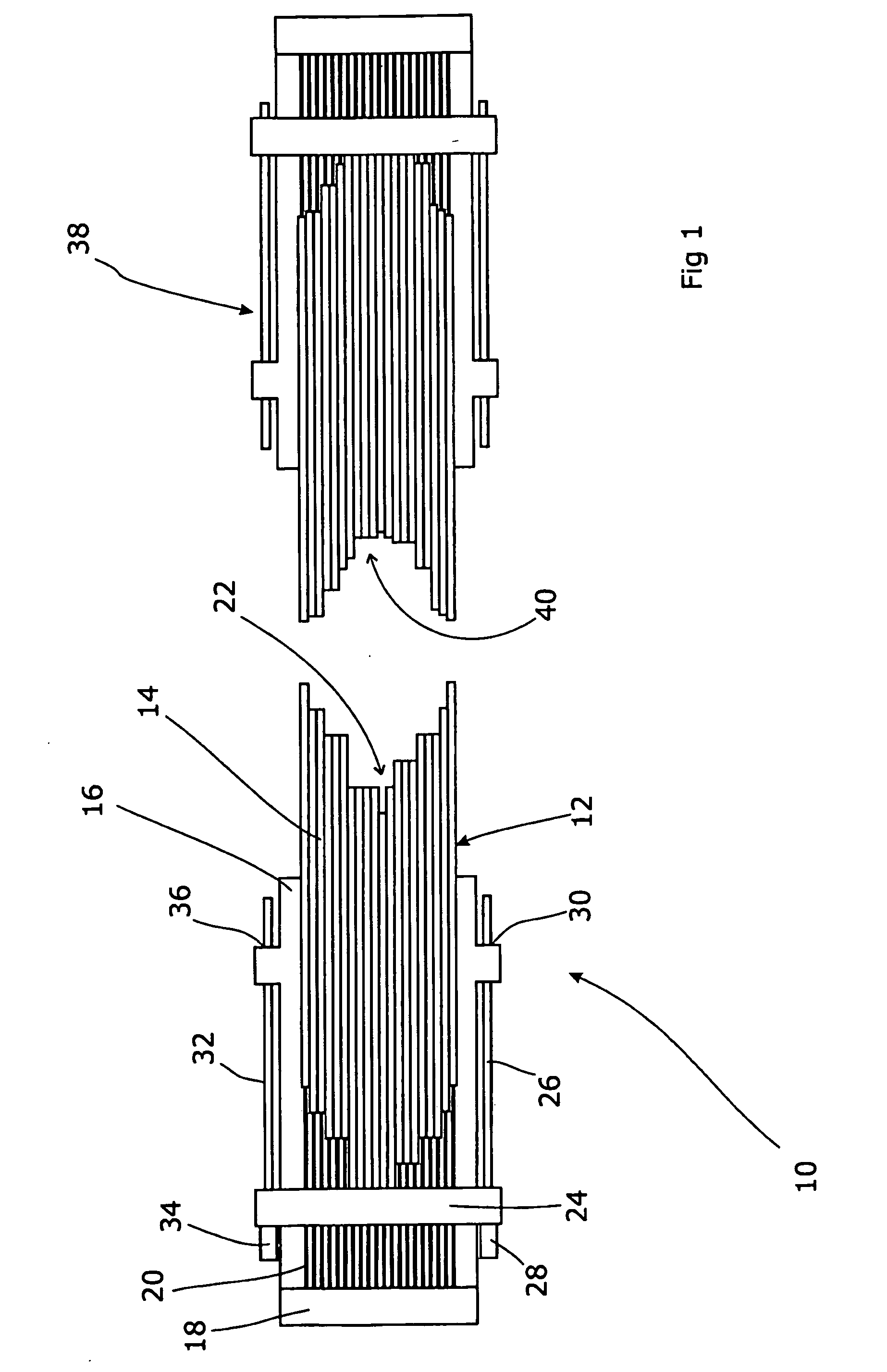
[0017]FIG. 1 shows an MLC 10 of the type to which the present application can be applied. A first bank 12 of elongate leaves 10 are arranged in a side-by-side array with their longitudinal edge arranged transverse to the beam, their depth arranged parallel to the beam, and their thicknesses transverse to the beam. Each leaf is mounted in a suitable guide (not shown) supported on a carriage 16. The guide is usually machined so as to support the upper and lower longitudinal edges of the leaves 14 and allow them to slide backwards and forwards in the longitudinal direction. A bank of motors 18, one for each leaf, each drive a leadscrew 20. Each leadscrew 20 engages with a captive nut or other threaded section within a leaf 14; thus as the motor 18 drives the leadscrew 20, this forces the captive nut along the leadscrew 20 and draws the relevant leaf 14 longitudinally backwards or forwards, depending on the direction of rotation of the motor.

[0018]In this way, the leaves 14 can be drive...


PUM


Abstract

A multi-leaf collimator for a radiotherapy apparatus comprises a plurality of elongate leaves mounted in a carriage, the carriage being mounted on a substrate, wherein the leaves are independently moveable relative to the carriage in a longitudinal direction, and the carriage is moveable in that direction relative to the substrate, and a control apparatus arranged to receive a signal representing leaf positions relative to the substrate and being arranged to control the leaf positions relative to the carriage and the carriage positions relative to the substrate so as to achieve those leaf positions relative to the substrate. By allowing the carriage to be driven concurrently with the leaves, the speed of movement of the carriage can be added to that of the leaves. In this way, where leaves are required to make a long traverse they can do so more quickly. Most MLCs have a means for sensing the current positions of the leaves relative to the substrate, such as an optical or mechanical positional feedback system. The control apparatus can therefore compare the current leaf positions to the signalled leaf positions, and move the leaves and the carriage accordingly. Each leaf can be moved according to a difference between the current leaf position and the signalled leaf position, and the carriage can be moved according to an average difference between the current leaf positions and the signalled leaf positions. A corresponding method is also disclosed.

Description

FIELD OF THE INVENTION[0001]The present invention relates to Multi-leaf Collimators.BACKGROUND ART[0002]A Multi-Leaf Collimator (MLC) is used in external beam radiation therapy in order to collimate the radiation beam to a chosen cross-sectional shape. The aim is to allow accurate delivery of the radiation to the tumour volume, and this is achieved by collimating the beam with an array of narrow elongate tungsten leaves, arranged side-by side and individually motorised in order to allow them to be moved longitudinally. This allows the collimator to define a desired shape.[0003]There are limitations on the longitudinal length of the leaves, dependent on their thickness. Generally, for a given leaf thickness (which does of course define the collimator resolution), there is a maximum feasible length of leaf. Beyond this length, difficulties arise in driving the leaf reliably. This therefore limits the maximum possible collimator aperture, and hence the size of the volume that can be tr...

Claims


Application Information

Patent Timeline
IPC IPC(8): G21K1/04
CPCA61N5/1042G21K1/046G21K1/04
Inventor FURTH, MARK ALEXANDERSMITH, ADRIAN MAXWELL
Owner ELEKTA AB
Why Eureka
Try Eureka