Wireless power feeder and wireless power transmission system

a technology of wireless power transmission system and wireless power feeder, which is applied in the direction of electromagnetic wave system, transformer, inductance, etc., can solve the problem of not being able to feed big electric power, and achieve the effect of suppressing the influence of resonance characteristics

Inactive Publication Date: 2011-03-03
TDK CORPARATION
View PDF57 Cites 158 Cited by
  • Summary
  • Abstract
  • Description
  • Claims
  • Application Information

AI Technical Summary

Benefits of technology

[0013]The use of the power circuit that operates as a switching power source for the feeding coil can enhance the efficiency of power transmission from the power circuit to feeding coil. When the drive frequency of the power circuit and resonance frequency are made coincide with each other, the power transmission efficiency in the entire system can be enhanced. The current phase is measured from current passing through a switch included in the power circuit, so that a measurement load is not directly applied to the feeding coil. Thus, it is possible to monitor whether a resonance state is maintained by detecting the phase difference between the voltage phase and current phase while suppressing influence on the resonance characteristics of the feeding coil.
[0034]According to the present invention, it is possible to detect the phase of supply power while suppressing influence on the resonance characteristics in a wireless power feeding technique of a magnetic resonance type.

Problems solved by technology

The type (B) utilizing radio wave is available in a long range; however, it cannot feed big electric power.

Method used


Image

  • Wireless power feeder and wireless power transmission system
  • Wireless power feeder and wireless power transmission system
  • Wireless power feeder and wireless power transmission system

Examples


first embodiment

Push-Pull Type

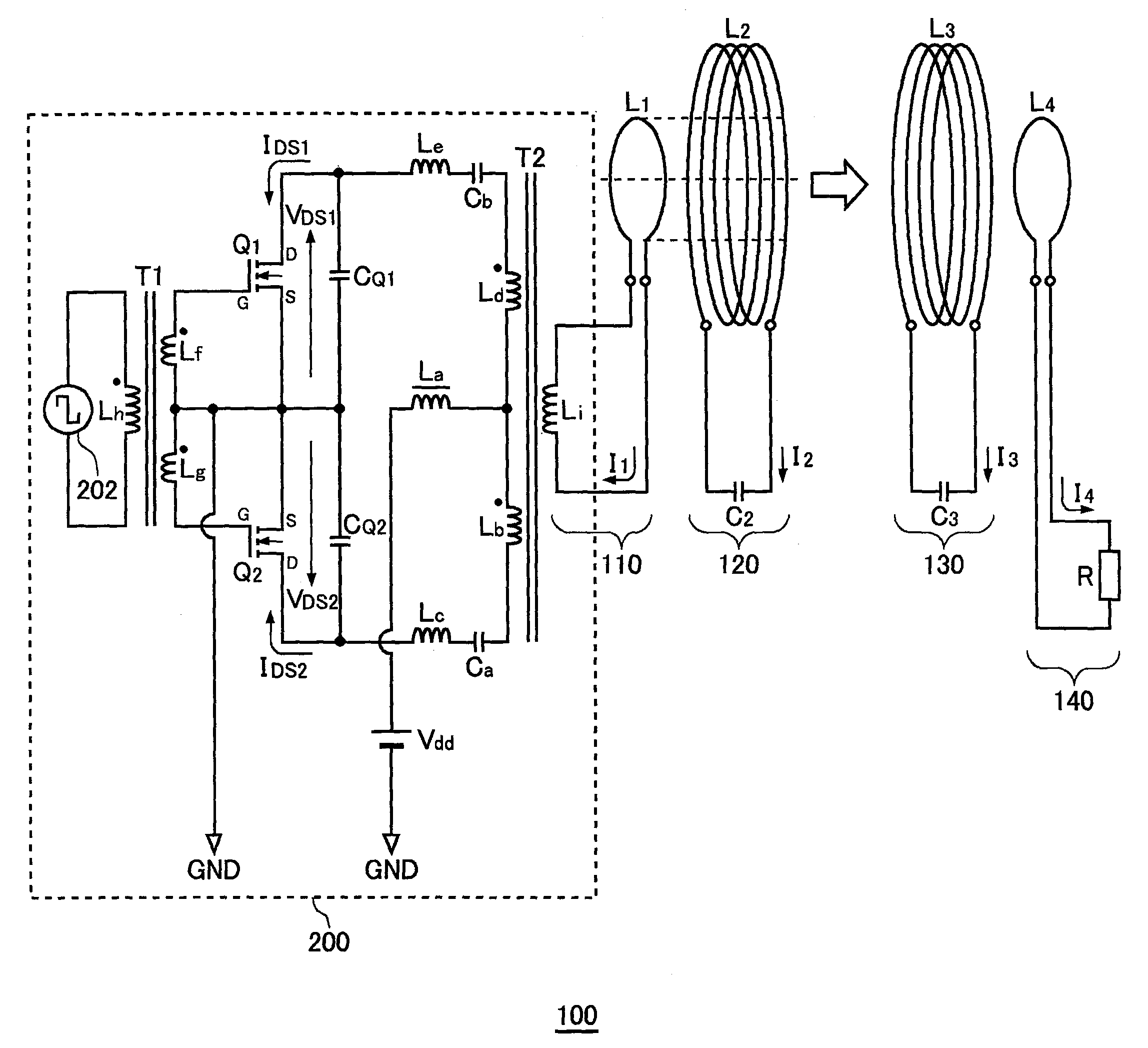
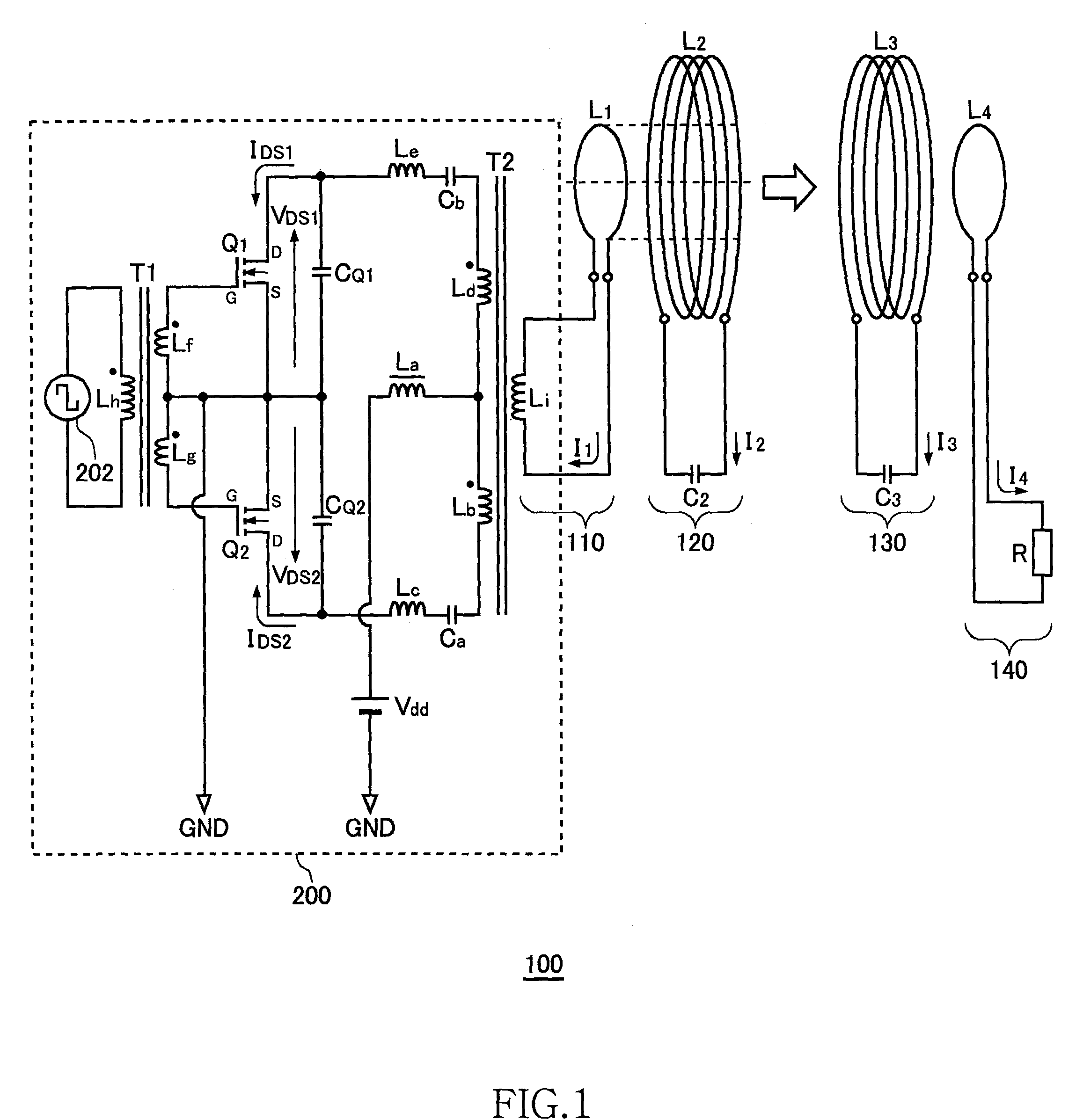
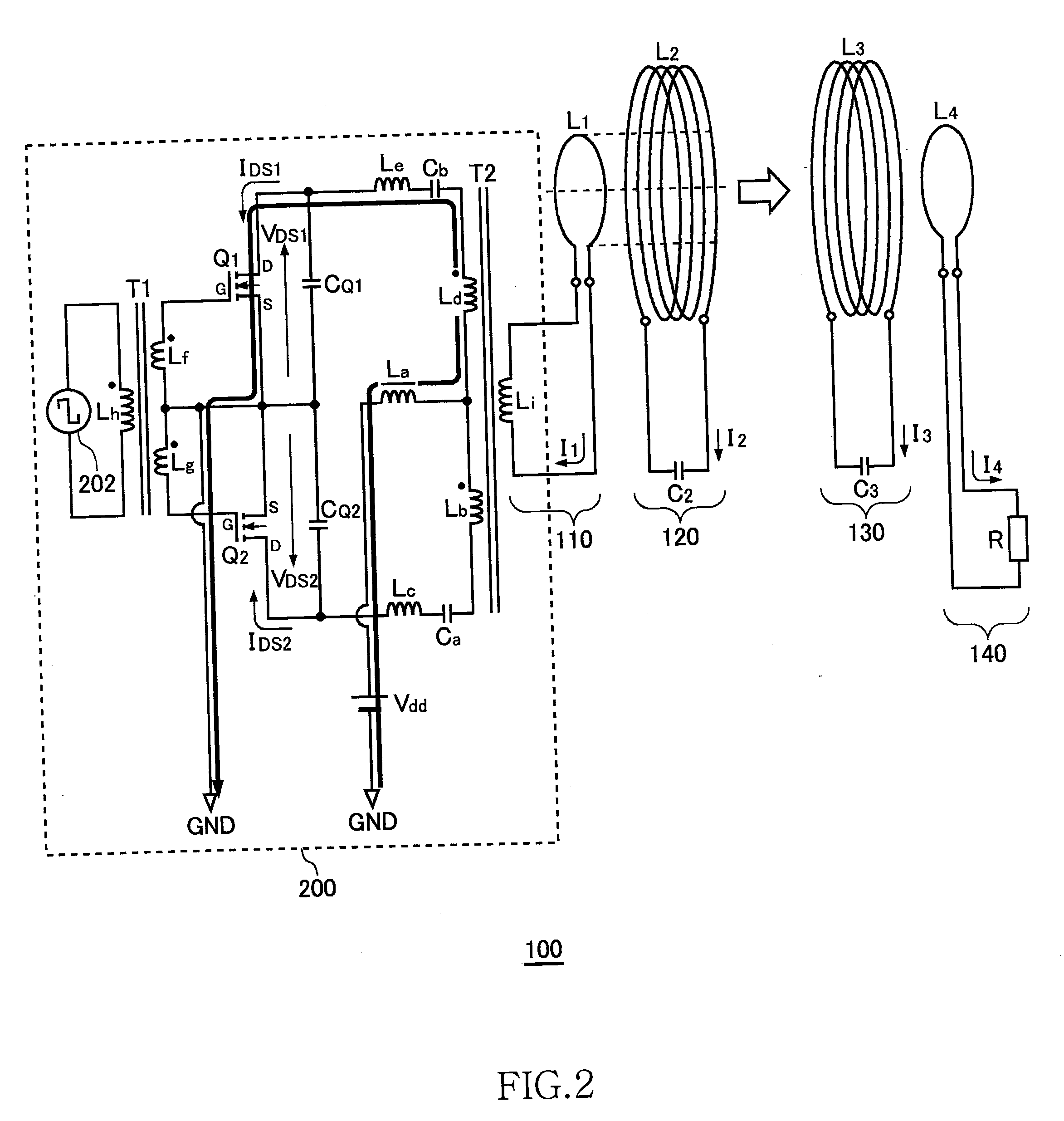
[0066]FIG. 1 is a system configuration view of a wireless power transmission system 100 without automatic drive frequency tracking function. The wireless power transmission system 100 includes a power circuit 200, an exciting circuit 110, a feeding coil circuit 120, a receiving coil circuit 130, and a loading circuit 140. A distance of several meters is provided between the feeding coil circuit 120 and receiving coil circuit 130. The wireless power transmission system 100 mainly aims to feed power from the feeding coil circuit 120 to receiving coil circuit 130 by wireless.

[0067]The wireless power transmission system 100 illustrated in FIG. 1 is assumed to operate at ISM (Industry-Science-Medical) frequency band. The following description will be made assuming that the resonance frequency fr of the feeding coil circuit 120 or receiving coil circuit 130 is 13.56 MHz within the ISM frequency band.

[0068]The exciting circuit 110 is a circuit in which an exciting coil L1 and...

second embodiment

Half-Bridge Type

[0118]FIG. 13 is a system configuration view of a wireless power transmission system 1100 according to a second embodiment. The wireless power transmission system 1100 includes, as basic components, a power circuit 1200, a receiving coil circuit 1130, and a loading circuit 1140. Further, the wireless power transmission system 1100 includes, as components for automatically adjusting the drive frequency fo, a first waveform rectifier 1142, a second waveform rectifier 1144, a phase detection circuit 1150, and a drive frequency tracking circuit 1152. The power circuit 1200 further includes a feeding coil L2. A distance of several meters is provided between the feeding coil L2 and receiving coil circuit 1130. The wireless power transmission system 1100 mainly aims to feed power from the feeding coil L2 to receiving coil circuit 1130 by wireless. The wireless power transmission system 1100 according to the second embodiment is assumed to operate at around 100 kHz. Thus, th...

third embodiment

Half-Bridge Type

[0168]FIG. 26 is a system configuration view of a wireless power transmission system 1106 according to a third embodiment. In the wireless power transmission system 1100 according to the second embodiment, the oscillator 1202 directly drive the feeding coil L2; while in the wireless power transmission system 1106 according to the third embodiment, the oscillator 1202 does not drive the feeding coil L2 but drives the exciting coil L1. The other components of the wireless power transmission system 1106 are the same as those in FIG. 13, etc. Components designated by the same reference numerals as those of FIG. 13, etc. have the same or corresponding functions as those in FIG. 13, etc.

[0169]A power circuit 1204 feeds AC power to the exciting coil L1 at the resonance frequency fr. The exciting coil L1 and capacitor C1 constitute a resonance circuit of the resonance frequency fr. A feeding coil circuit 1120 is a circuit in which the feeding coil L2 and capacitor C2 are con...


PUM


Abstract

Power is transmitted from a feeding coil L2 to a receiving coil L2 by magnetic resonance. A power circuit 200 turns ON / OFF switching transistors Q1 and Q2 to feed AC current to an exciting circuit 110, whereby the AC power is fed from an exciting coil L1 to a feeding coil L2. A phase detection circuit 150 sets the switching transistor Q2 of the power circuit 200 as a measurement target and detects the phase difference between source-drain current IDS2 and source-drain voltage VDS2 from the current phase and voltage phase thereof.

Description

BACKGROUND OF THE INVENTION[0001]1. Field of the Invention[0002]The present invention relates to a wireless power feeder for feeding power by wireless and a wireless power transmission system.[0003]2. Description of Related Art[0004]A wireless power feeding technique of feeding power without a power cord is now attracting attention. The current wireless power feeding technique is roughly divided into three: (A) type utilizing electromagnetic induction (for short range); (B) type utilizing radio wave (for long range); and (C) type utilizing resonance phenomenon of magnetic field (for intermediate range).[0005]The type (A) utilizing electromagnetic induction has generally been employed in familiar home appliances such as an electric shaver; however, it can be effective only in a short range of several centimeters. The type (B) utilizing radio wave is available in a long range; however, it cannot feed big electric power. The type (C) utilizing resonance phenomenon is a comparatively ne...

Claims


Application Information

Patent Timeline
Patent Type & Authority Applications(United States)
IPC IPC(8): H02J17/00
CPCH02J5/005H02M7/539H02M7/5381Y02B70/1441H02M2007/4815Y02B70/10H02M7/4815H02J50/12
Inventor URANO, TAKASHI
Owner TDK CORPARATION
Why Eureka
Try Eureka