Divide-by-two injection-locked ring oscillator circuit

Inactive Publication Date: 2011-03-03
QUALCOMM INC
View PDF17 Cites 67 Cited by
  • Summary
  • Abstract
  • Description
  • Claims
  • Application Information

AI Technical Summary

Benefits of technology

[0012]In a fourth embodiment, a frequency divider with improved output signal slew rate is realized. In this embodiment, the frequency divider involves two ILROs. The frequency divider receives a differential input signal, divides the input signal in frequency by the integer two, and outputs two differential output signals, I and Q, in phase quadrature. An Alternating Current (AC) coupling capacitor couples the source of the first transistor of the cross-coupled pair of the first ILRO to the gate of a third transistor. The source of the third transistor is coupled to a current source. The drain of the third transistor is coupled to the drain of the first transistor of the cross-coupled transistor pair of the second ILRO. In this manner, the signal present at the source of the first tr

Problems solved by technology

Although, the circuit of FIG. 1 operates satisfactorily in some applications, it has limitations.
Due to the use of inductive loads, the physical size of a conventional ILFD is undesirably large.
In addition, the range of input frequencies to which the conventional ILFD will reliably “lock”, and hence divide, is limited to a relatively small percentage of the center tuned input frequency for typical input signal amplitudes.
A broader range can be achieved by increasing the input signal amplitude or reducing the inductor quality factor but this approach consumes more power.
An elaborate digitally controlled capacitor tuning bank may be employed to broaden the effective range of the ILFD to a practical range of 30-40% of the center tuned input frequency, but this approach is undesirably complex and consumes die area.
A

Method used


Image

  • Divide-by-two injection-locked ring oscillator circuit
  • Divide-by-two injection-locked ring oscillator circuit
  • Divide-by-two injection-locked ring oscillator circuit

Examples


third embodiment

[0041]FIG. 10 is illustrative of a divide by four operation of frequency divider 113 in a In the present example, frequency divider 113 includes ILRO 130, ILRO 142, and ILRO 162. As depicted in FIG. 10, ILRO 130 and ILRO 142 are as described in FIG. 6 and ILRO 162 is analogous to ILRO 130. Output signal I− is present at oscillating node 140 of ILRO 130 and is communicated from frequency divider 113 on conductor 132. Output signal I+ is present on oscillating node 141 of ILRO 130 and is communicated from frequency divider 113 on conductor 133. Output signal Q− is present at oscillating node 146 of ILRO 142 and is communicated from frequency divider 113 on conductor 144. Output signal Q+ is present on oscillating node 147 of ILRO 142 and is communicated from frequency divider 113 on conductor 145. Input signal I1+ is present on input node 167 of ILRO 162. Input node 167 is coupled to conductor 131, and input signal I1+ is received by frequency divider 113 on conductor 131. Oscillatin...

second embodiment

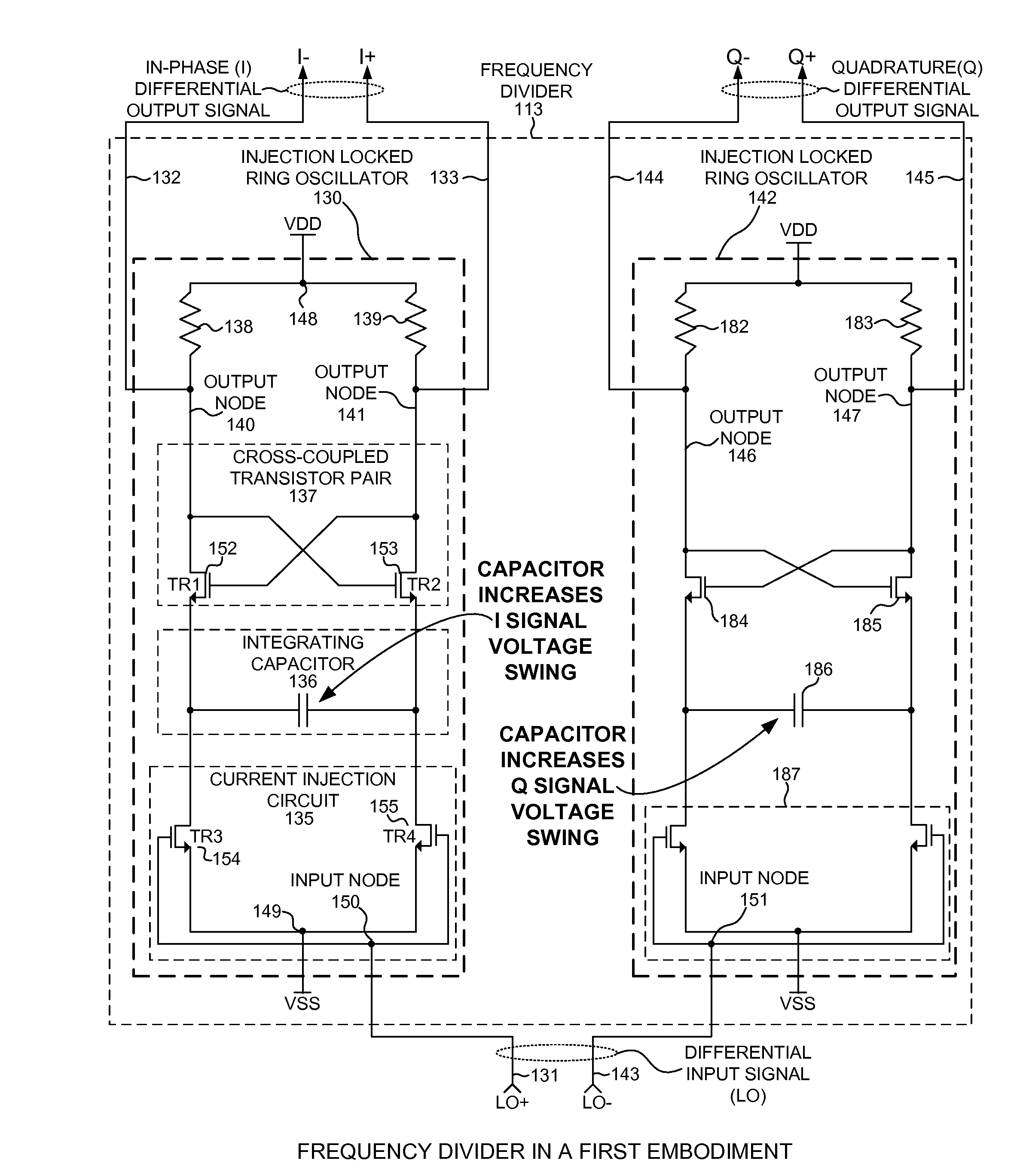
[0042]ILRO 162 receives oscillatory input signal I1+ over conductor 131 and performs a divide by two operation in frequency as discussed above with respect to ILRO 130. ILRO 162 outputs differential output signal LO as divided down oscillatory signal LO+ present on output node 165 and divided down oscillatory signal LO− present on output node 166. ILRO 130 and ILRO 142 are clocked on opposite phases of input signal LO due to the communication of the LO+ signal from node 165 to input voltage node 150 of ILRO 130 on conductor 163 the communication of the LO− signal from node 166 to input voltage node 151 of ILRO 142 on conductor 164. ILRO 130 receives oscillatory input signal LO+, performs a divide by two operation in frequency, and outputs divided down oscillatory signals I+, I−. Similarly, ILRO 142 receives oscillatory input signal LO−, performs a divide by two operation in frequency, and outputs divided down oscillatory signals Q+, Q−. Signals I+, I−, Q+, and Q− are in phase quadra...

fourth embodiment

[0043]FIG. 11 is illustrative of frequency divider 113 in a In the present example, frequency divider 113 includes ILRO 130 and ILRO 142. As depicted in FIG. 11, ILRO 130 and ILRO 142 are as described in FIG. 6, however, in the present example additional elements are included. ILRO 130 includes transistors 174 and 175. The source of transistor 174 and the source of transistor 175 are coupled to a first lead of current source 180. A second lead of current source 180 is coupled to circuit supply voltage source, VSS. The gate of transistor 174 is coupled to oscillating node 160 of ILRO 130 via Alternating Current (AC) coupling capacitor 172. AC coupling capacitor 172 is sized to block Direct Current (DC) offset voltage signals and pass high frequency (Alternating Current) AC voltage signals. Similarly, AC coupling capacitor 173 couples the gate of transistor 175 to oscillating node 161 of ILRO 130. The drain of transistor 174 is coupled to oscillating node 146 of ILRO 142. As coupled ...


PUM


Abstract

A frequency divider involves a plurality of Injection-locked Ring Oscillators (ILRO). A first ILRO includes a pair of cross-coupled N-channel transistors, a pair of load resistors, an integrating capacitor, and a current injection circuit. The drain of each transistor is coupled to the gate of the other transistor. Each load resistor couples the drain of each transistor to a circuit voltage source. The integrating capacitor couples the sources of each transistor. The current injection circuit alternately opens and closes a path from the source of each transistor to circuit ground in response to an oscillatory input signal of a first frequency. In response, the voltage state at the drain of each transistor is alternately latched and toggled, generating a differential pair of oscillating signals frequency divided by two. A first and second ILRO driven in antiphase generate two differential output signals in phase quadrature.

Description

BACKGROUND INFORMATION[0001]1. Technical Field[0002]The disclosed embodiments relate generally to frequency dividers, including frequency dividers operable in wireless communication systems.[0003]2. Background Information[0004]For some applications, such as wireless communication systems it is useful to include a frequency divider circuit. In one example, a frequency divider receives an oscillatory input signal, frequency divides the input signal, and generates a divided-down oscillatory output signal. The frequency division is characterized as frequency division by an integer. Within a wireless communication system, frequency dividers see frequent use as part of a radio transceiver (transmitter / receiver). In one example within a radio transceiver, a frequency divider may be used to receive an oscillatory signal from a Local Oscillator (LO), divide-down the oscillatory signal in frequency, and generate two lower frequency output signals: a differential in-phase (I) output signal and...

Claims


Application Information

Patent Timeline
IPC IPC(8): H03B19/12
CPCH03B27/00H03B5/1228H03B2200/0078H03B2200/0074H03B5/1212H03B5/12
Inventor FAGG, RUSSELL J.
Owner QUALCOMM INC
Why Eureka
Try Eureka