Wind-turbine blade

Inactive Publication Date: 2011-03-03
MITSUBISHI HEAVY IND LTD
View PDF8 Cites 61 Cited by
  • Summary
  • Abstract
  • Description
  • Claims
  • Application Information

AI Technical Summary

Benefits of technology

[0014]Since the wind-turbine blade is transported in fabricated units, transporter vehicles can be readily procured and the selection of roads is facilitated. Since this allows for efficient transportation, the transportation time can be shortened, and cost reduction can be achieved.
[0015]Because the opening formed in the main-body skin is blocked off by the blocking plate, dust, sand, dirt, and the like are prevented from entering the hollow interiors during transportation. Therefore, since a process for removing dust, sand, dirt, and the like becomes unnecessary during assembly of the wind-turbine blade, the time required for such a process can be eliminated.
[0016]The assembly process of the wind-turbine blade at the installation site is performed by co

Problems solved by technology

Such large blades cause various kinds of difficulties, such as a difficulty in fabricating each blade as a single

Method used


Image

  • Wind-turbine blade
  • Wind-turbine blade
  • Wind-turbine blade

Examples


first embodiment

[0056]A wind turbine generator 1 according to a first embodiment of the present invention will now be described with reference to FIGS. 1 to 3.

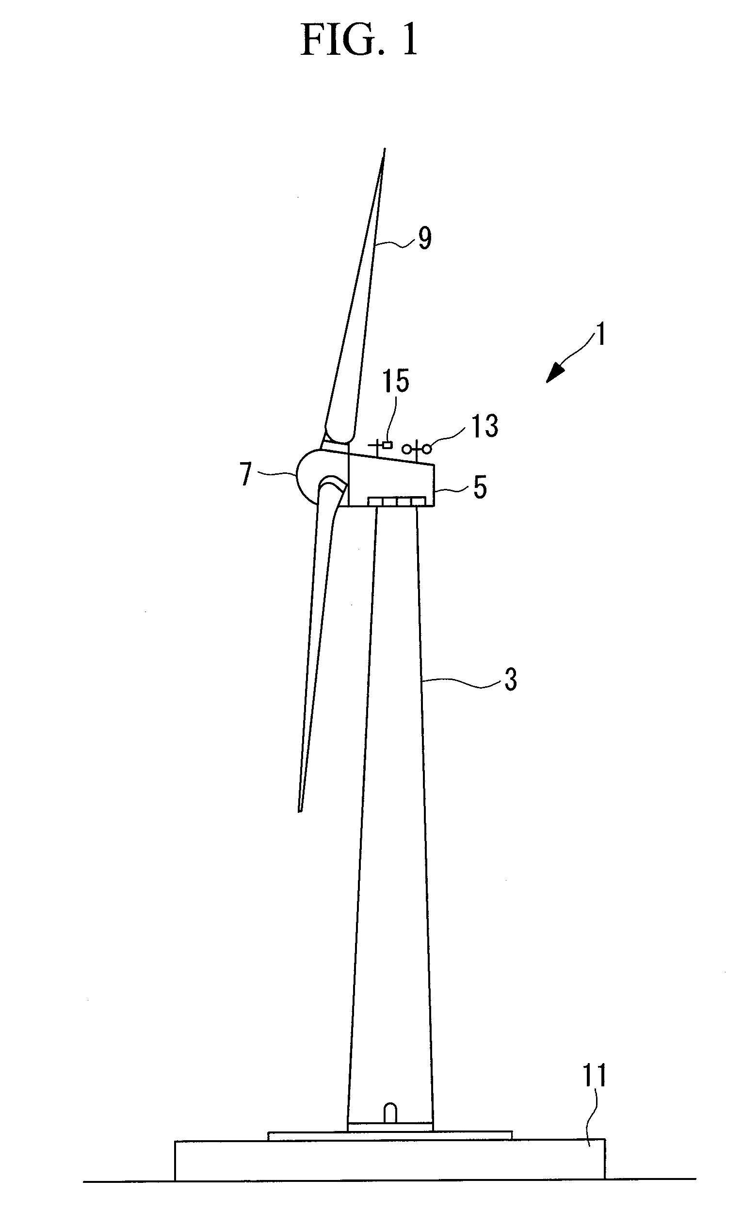
[0057]FIG. 1 is a side view illustrating the overall schematic configuration of the wind turbine generator 1.

[0058]As shown in FIG. 1, the wind turbine generator 1 includes a tower 3 standing upright on a foundation 11, a nacelle 5 disposed on the top of the tower 3, a hub 7 provided in the nacelle 5 in a rotatable manner about a rotation axis extending substantially in the horizontal direction, and multiple, e.g., three, wind-turbine blades 9 attached to the hub 7 so as to extend radially around the rotation axis thereof.

[0059]The force of wind striking the wind-turbine blades 9 in the rotation-axis direction of the hub 7 is converted to power that rotates the hub 7 about the rotation axis.

[0060]An anemometer 13 that measures the ambient wind speed value, an anemoscope 15 that measures the wind direction, and a lightning rod (not shown) are ...

second embodiment

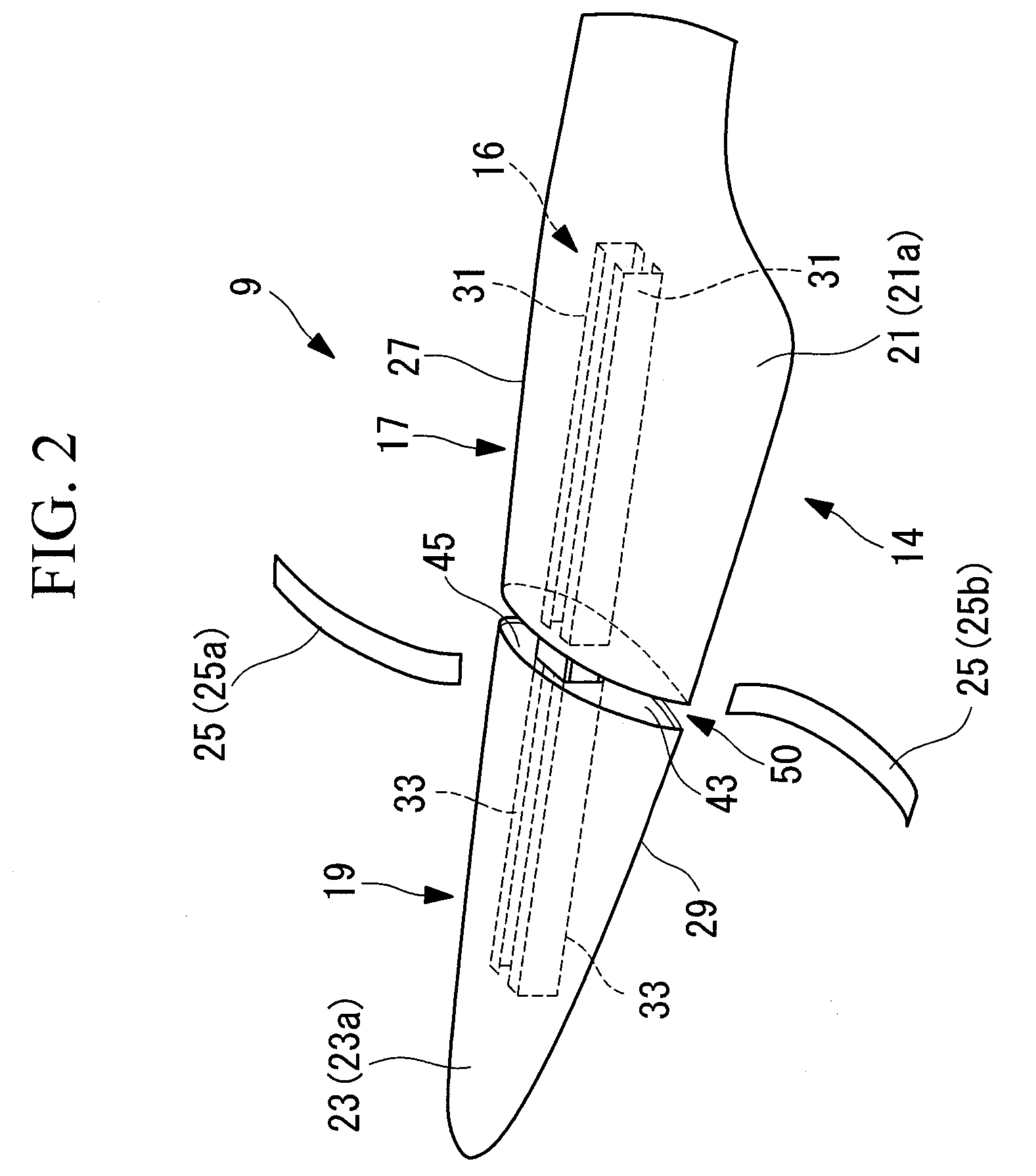
[0108]Next, a wind-turbine blade 9 according to a second embodiment of the present invention will be described with reference to FIGS. 4 to 6.

[0109]In this embodiment, since the configurations of a main spar 16 and the joint structure are different from those in the first embodiment, the following description will mainly be directed to these differences, and redundant descriptions of sections that are the same as those in the first embodiment described above will be omitted. Components that are the same as those in the first embodiment will be given the same reference numerals.

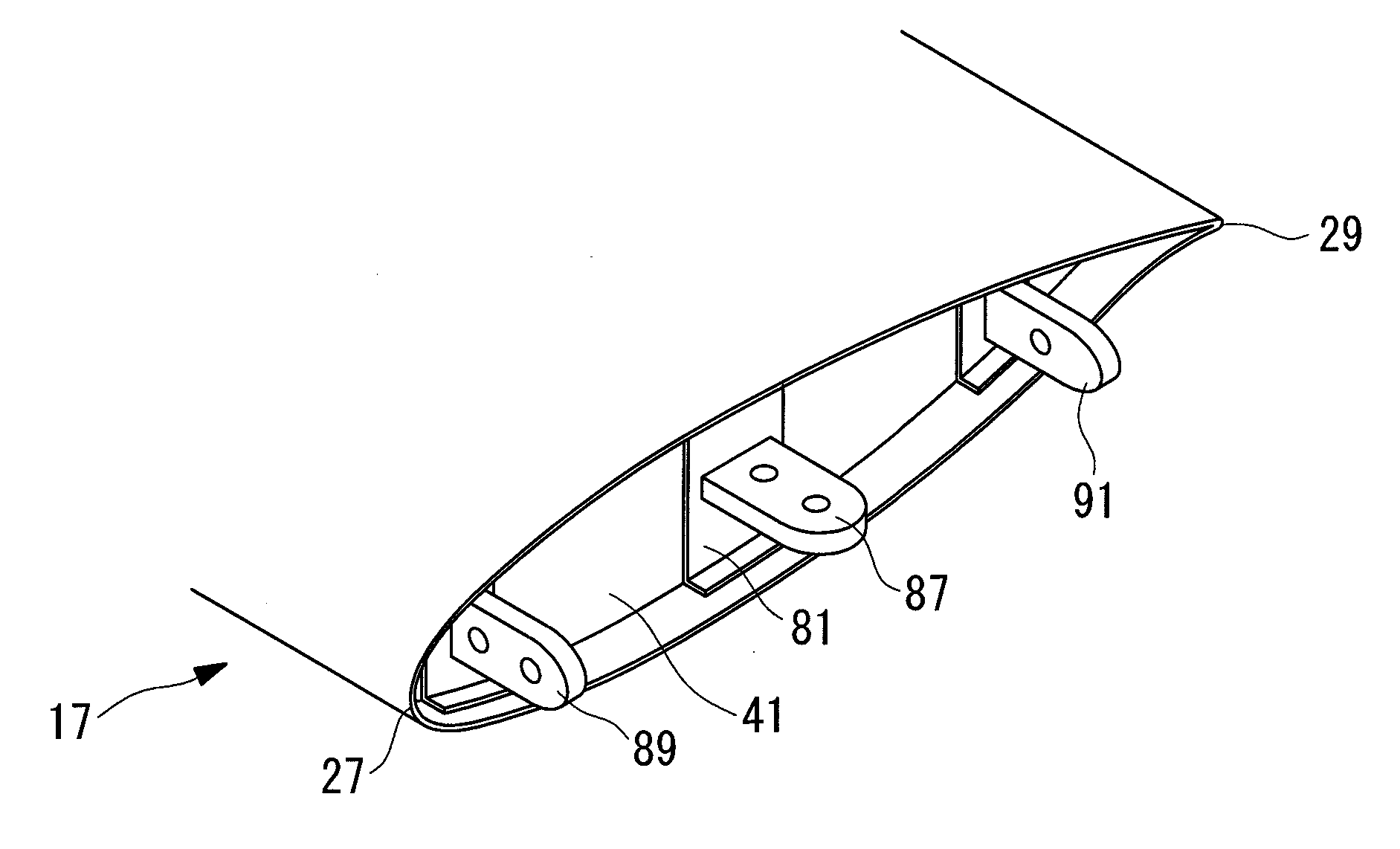
[0110]In this embodiment, a single hollow main spar 16 having a rectangular shape in cross section is provided. Connection sections 50 are provided with a connecting member 63 that joins a blade-root-side main spar 31 and a blade-tip-side main spar 33 to each other. The connecting member 63 has a substantially rectangular parallelepiped shape that is hollow, and is configured to receive the blade-root-side mai...

third embodiment

[0120]Next, a wind-turbine blade 9 according to a third embodiment of the present invention will be described with reference to FIGS. 9 and 10.

[0121]In this embodiment, since the configurations of a main spar 16 and the joint structure are different from those in the first embodiment, the following description will mainly be directed to these differences, and redundant descriptions of sections that are the same as those in the first embodiment described above will be omitted. Components that are the same as those in the first embodiment will be given the same reference numerals.

[0122]In this embodiment, a blade-root-side main spar 31 is formed of two blade-root-side main spar sections 31 integrated with each other at ends thereof at the blade-tip side and has a rectangular shape in cross section. A blade-tip-side main spar 33 is formed of two blade-tip-side main spar sections 33 integrated with each other at ends thereof at the blade-root side, and has a rectangular shape in cross s...


PUM


Abstract

A wind-turbine blade that prevents foreign matter from entering the inside thereof during transportation and that can be efficiently assembled in good condition is provided. A wind-turbine blade includes a skin that forms a long and hollow shape, and a main spar that extends in the longitudinal direction and reinforces the skin from the inside thereof. The main spar is divided into a blade-root-side main spar and a blade-tip-side main spar in the longitudinal direction; the blade-root-side main spar and the blade-tip-side main spar have connection sections that are connected to each other; the skin is divided into a connection-section skin, located at a position corresponding to the connection sections, a blade-root-side skin, and a blade-tip-side skin; and openings formed in the blade-root-side skin and the blade-tip-side skin are blocked off by blanking plates.

Description

RELATED APPLICATIONS[0001]The present application is national phase of International Application Number PCT / JP2009 / 064879, filed Aug. 26, 2009, and claims priority from Japanese Application Number 2008-227372 filed Sep. 4, 2008.TECHNICAL FIELD[0002]The present invention relates to wind-turbine blades.BACKGROUND ART[0003]In recent years, wind turbine generators have increased in size for enhancing their electricity generation efficiency and for generating more electricity. An increase in the size of wind turbine generators has caused a corresponding increase in the size of wind-turbine blades; for example, the blade length is 40 meters or more.[0004]Such large blades cause various kinds of difficulties, such as a difficulty in fabricating each blade as a single unit and a difficulty in transportation since it is difficult to ensure roads, transporter vehicles, and the like.[0005]In order to overcome such difficulties, examples of wind-turbine blades that are divided into segments in ...

Claims


Application Information

Patent Timeline
IPC IPC(8): F03D11/00
CPCF03D1/0675F03D1/0683F05B2260/63Y02E10/721Y02E10/722F05B2240/302Y02E10/72F05B2230/60
Inventor KAWASETSU, NOZOMUESAKI, KOUJIKUROIWA, TAKAOHORI, SHINICHI
Owner MITSUBISHI HEAVY IND LTD
Why Eureka
Try Eureka