Process for Producing High-Quality Melamine from Urea

Inactive Publication Date: 2011-03-03
CASALE SA
View PDF9 Cites 5 Cited by
  • Summary
  • Abstract
  • Description
  • Claims
  • Application Information

AI Technical Summary

Benefits of technology

[0042]The mechanical agitators are preferably impellers with a magnetic driving, which is per se known, to avoid the problem of sealing the agitators. To promote the full-baffled condition of the liquid phase, each of said vessel, or each of said compartments, is provided with internal vertical baffles, to impede the rotation of the agitated liquid mass, enhancing the shear effect of the impeller and therefore the mass and heat transfer rates. In still preferred embodiments, the melted urea is fed near and above the blades of the impeller of the first stage, while added gaseous ammonia is fed below the blades of impellers of the first and second stage.
[0043]The above two-stage conversion process has been found surprisingly efficient. Due to the mechanical agitation and the feed of molten urea to the first stage, the molten urea is dispersed in the reaction mass in a very effective manner and instantaneously, avoiding the formation of infusible products. Mo

Problems solved by technology

Another problem is the need of a good and immediate dispersion of urea in the hot melamine melt, to avoid formation of infusible by-products; the urea feed must also be converted as much as possible, to minimise the unconverted

Method used


Image

  • Process for Producing High-Quality Melamine from Urea
  • Process for Producing High-Quality Melamine from Urea
  • Process for Producing High-Quality Melamine from Urea

Examples


first embodiment

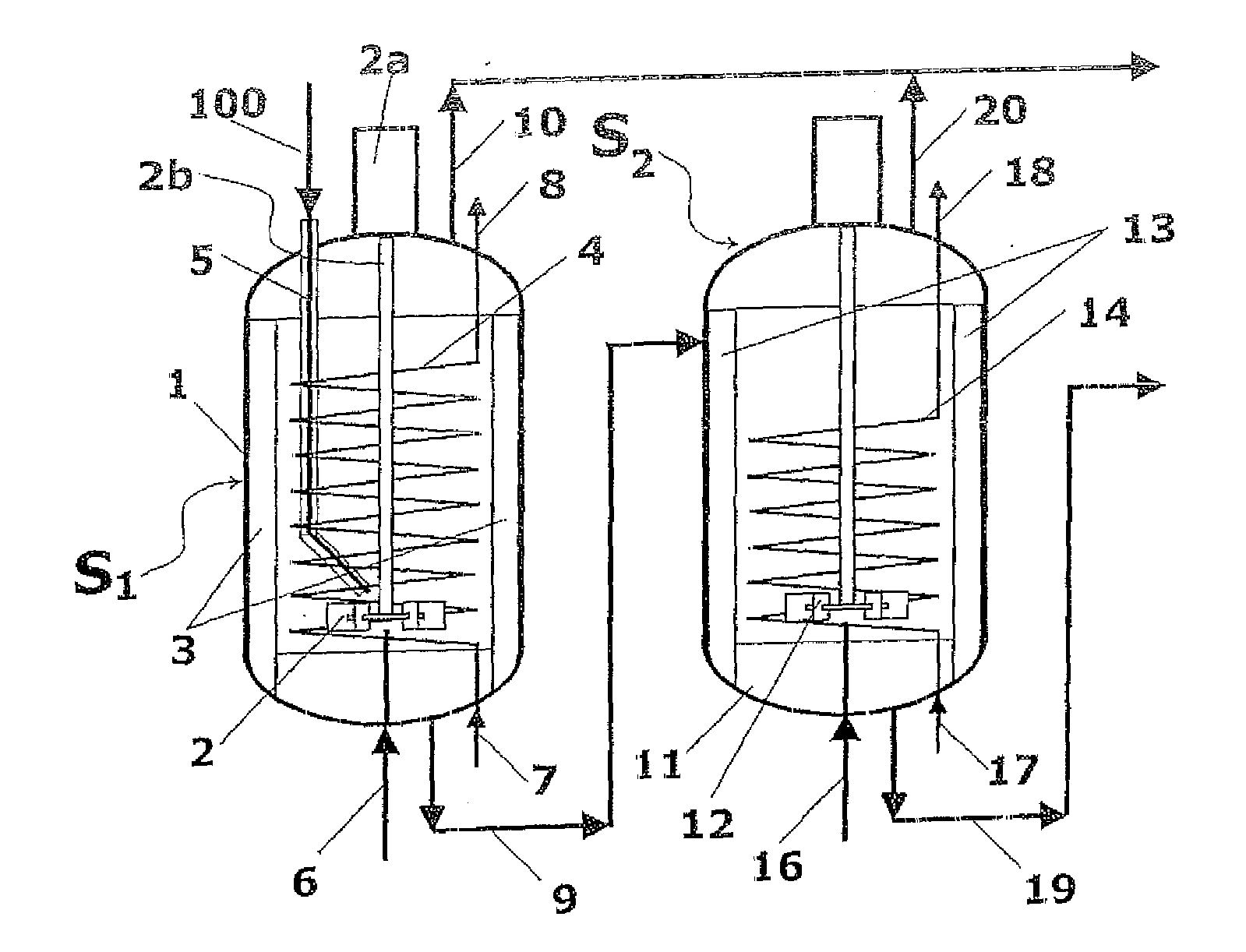
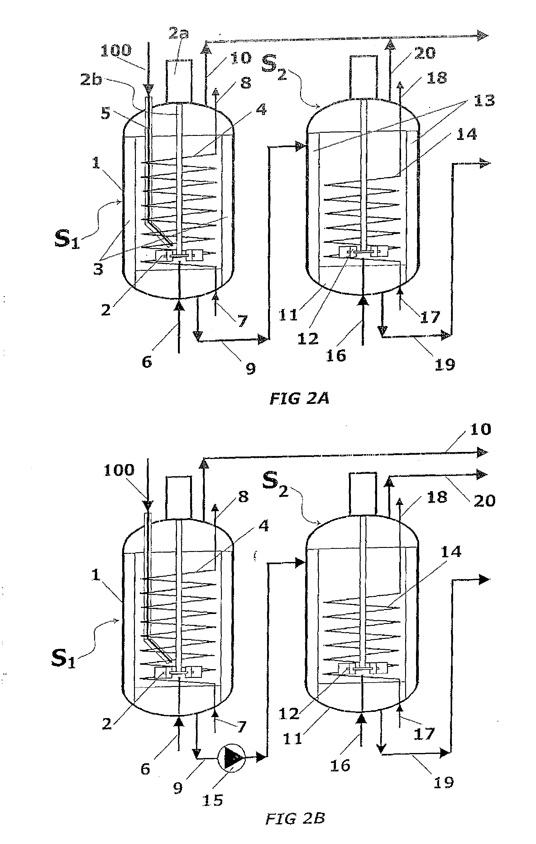
[0061]Referring to FIG. 2A, reaction zones S1 and S2 are obtained with a first stirred vessel 1 and a second stirred vessel 11 connected by a melamine melt line 9. Molten urea feed 100 is introduced via urea duct 5 into the first vessel 1. Further ammonia (streams 101, 104 of FIG. 1) is added via lines 6 and 16 to the liquid phase in both vessels 1 and 11. Gaseous products, mainly comprising ammonia and CO2, are collected at lines 10 and 20, respectively. Melamine melt is obtained at line 19, i.e. at the output of the second vessel 11.

[0062]The vessel 1 is provided with a mechanical impeller 2, and vertical baffles 3 to maintain agitation of the liquid phase. The impeller 2 has a driving motor 2a and a shaft 2b extending inside the vessel 1. Said baffles 3 are appropriate to realize a “fully baffled condition”, where the tangential entrainment of liquid is impeded, and the cylindrically rotating vortex disappears, allowing transfer of a significant deal of power to the liquid under ...

second embodiment

[0075]The process is carried out in a single vessel, in order to compact the equipment and save construction expenses. In particular, the two reaction stages are operated inside two compartments C1 and C2 of a single, horizontal pressure vessel 21. The two compartments C1 and C2 correspond to reaction zones 51 and S2; they may differ in volume, although having the same cross section, by occupying a different length of the horizontal vessel 21. A baffle 22 separates the two compartments, while not closing completely the cross section of the vessel 21 and leaving a relatively small bottom passage 26.

[0076]For the sake of simplicity, items equivalent to those of the first embodiment of FIGS. 2A and 2B are indicated with the same numerals. Each compartment C1, C2 is provided with a mechanical agitator, respectively 2 and 12. Each compartment is also provided with baffles, respectively 3 and 13, to realise the “fully baffled condition” as above described. Heat is supplied to the first co...

third embodiment

[0078]In this embodiment, first and the second reaction zones are obtained with multiple stirred reactors arranged in cascade or in series. The advantage is that, at equality of plant production capacity, the same reaction completion is achieved in a reduced total volume of liquid. The number of vessels in series constituting each stage may be conveniently limited to two or three items.

[0079]Referring to example of FIG. 4, a first stage is formed by vessels 31A, 31B and 31C in cascade, and a second stage is formed by two further vessels 32A and 32B also in cascade. The three vessels 31A to 31C provide the first reaction zone S1 and perform the same process as reactor 1 in FIG. 2A; the two vessels of the second stage provide the second reaction zone S2 and perform the same process as reactor 11 in the same FIG. 2A. The molten urea feed 100 enters the first vessel 31A via a pipe 33, while gaseous ammonia is fed and subdivided to all vessels of the series in 34A, 34B, 34C and, respecti...


PUM


Abstract

A process for high-pressure, liquid phase conversion of urea into melamine is disclosed, where molten urea is fed to a first reaction zone (S1) where the melamine melt is under mechanical agitation, and a heat input (Q1) is provided to maintain the endothermic reaction, and the liquid is then passed to a second reaction zone (S2) kept at a lower temperature and where further agitation is provided. Embodiments of plants adapted to carry out the process are also disclosed, including multiple stirred reactors in cascade and a single reactor with multiple internal compartments defining said first and second reaction zones.

Description

FIELD OF THE INVENTION[0001]The invention relates to a process for converting urea into melamine in a high-pressure liquid phase, and to a reactor or a system of reactors for carrying out the inventive process.PRIOR ART[0002]Melamine (C3H6N6) is industrially produced from urea, by a strongly endothermic chemical reaction, at temperature about 400° C., that can be summarized as follows:6CO(NH2)2→C3N6H6+6NH3+3CO2 i.e. six moles of urea are converted into one mole of melamine plus ammonia and carbon dioxide. Melamine users require a commercial product of very high purity, usually not less than 99.8%, so that the process must be developed in order to remove impurities and avoid as much as possible the formation of by-products.[0003]The known art basically provides two processes for carrying out the above reaction, namely the low-pressure process, usually below 10 bar, and in presence of catalysts (catalyzed gas-phase process), and the high-pressure liquid phase process, where conversion...

Claims


Application Information

Patent Timeline
IPC IPC(8): C07D251/32B01J19/00
CPCB01J19/0013B01J10/005B01J19/006B01J19/0066B01J19/18B01J2219/0004B01J2219/00083B01J2219/00135B01J2219/00189B01J2219/00768B01J2219/182B01J2219/185B01J2219/1943C07D251/60B01J19/002
Inventor SIOLI, GIANCARLO
Owner CASALE SA
Why Eureka
Try Eureka