Eureka AIR delivers breakthrough ideas for toughest innovation challenges, trusted by R&D personnel around the world.

Active stress control during rapid shut down

Inactive Publication Date: 2011-03-10
RAYTHEON TECH CORP
View PDF11 Cites 1 Cited by
  • Summary
  • Abstract
  • Description
  • Claims
  • Application Information

AI Technical Summary

Benefits of technology

[0005]Briefly, in accordance with one embodiment of the disclosure, thermal stress within a condenser is reduced at system shutdown by responsively causing the liquid refrigerant to flow in reverse, from the evaporator to the condenser to thereby limit the temperature rise that would otherwise result in the condenser.

Problems solved by technology

However, because of the differences in the vessel and the tube materials, and their associated expansion coefficients, stress is created in such structures by their exposure to different temperatures and / or temperature difference from the manufacturing reference conditions.
The problem of thermal stress becomes more serious during periods of emergency shut down when the cooling water is no longer flowing through the condenser, but, because of the continued heat transfer and vaporization within the evaporator, hot refrigerant vapor continues to flow into the condenser, elevating the material temperatures

Method used


Image

  • Active stress control during rapid shut down
  • Active stress control during rapid shut down

Examples


Embodiment Construction

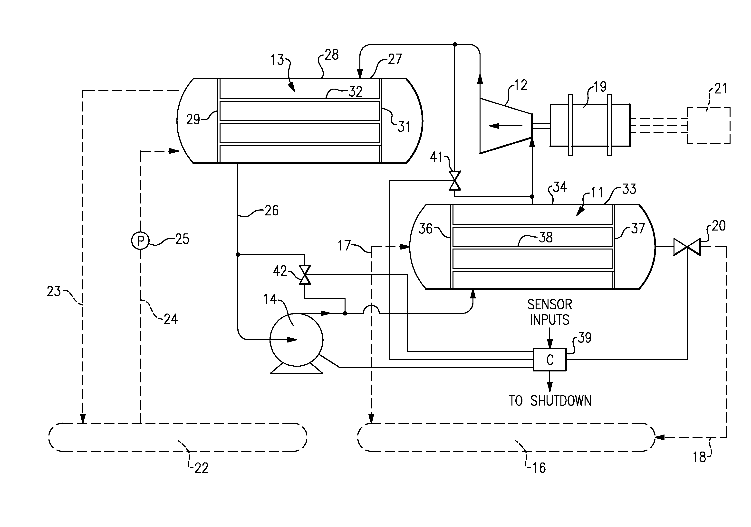
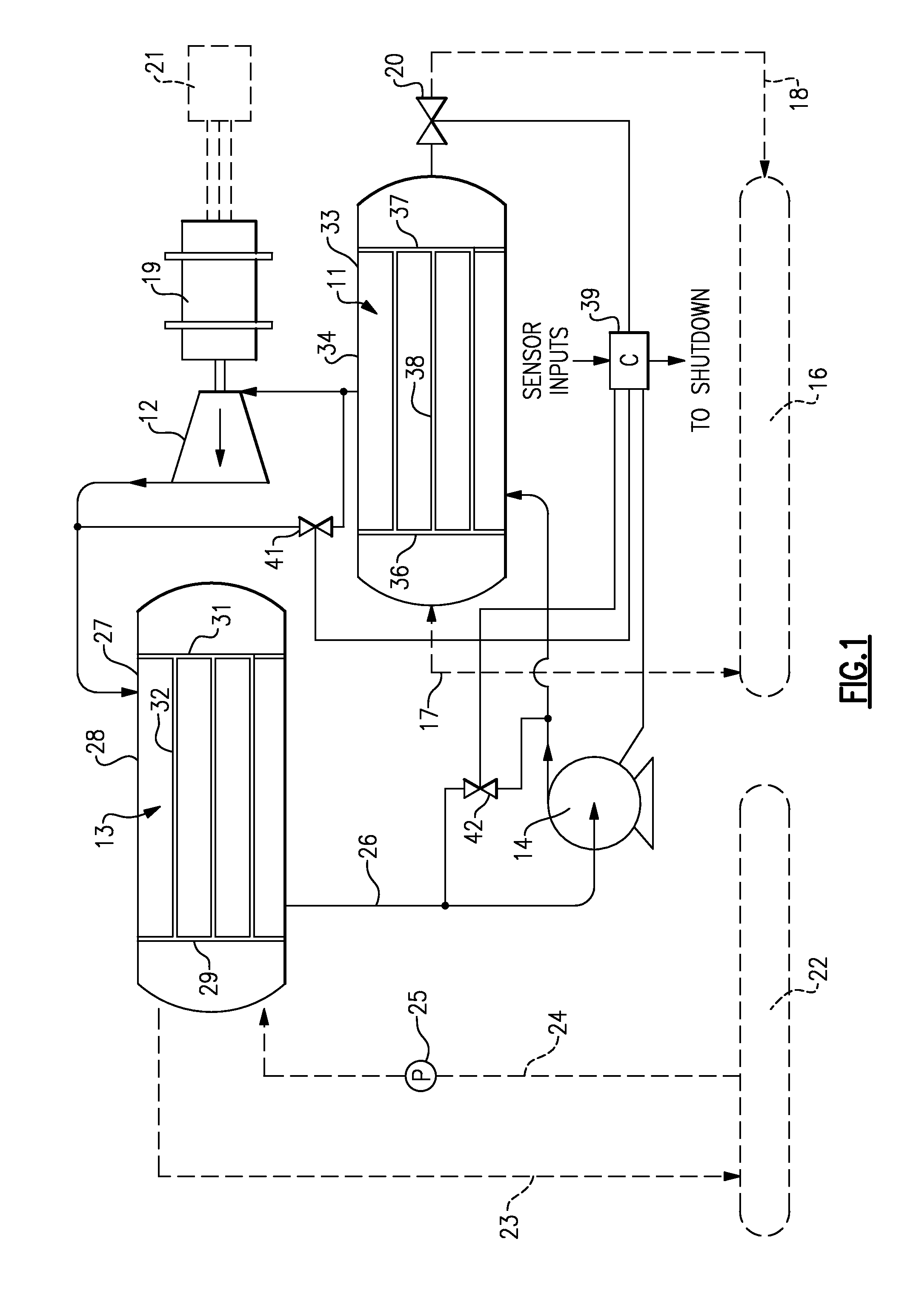
[0008]Shown in FIG. 1 is a vapor expansion system in the form of an organic rankine cycle system (ORC) which includes, in serial working-fluid-flow relationship, an evaporator 11, a turbine 12, a condenser 13 and a pump 14. The working fluid flowing therethrough can be of any suitable refrigerant such as refrigerant R-245fa, R134, pentane, for example.

[0009]The energy which is provided to drive the system is from a primary heat source 16 by way of a closed loop which connects to the evaporator 11 by way of lines 17 and 18. A valve 20 is provided to turn this flow on or off and may be located either upstream or downstream from the heat exchanger 16. The primary heat source 16 may be of various types such as, for example a geothermal source, wherein naturally occurring hot fluids are available below the surface of the earth.

[0010]After the working fluid is heated in the evaporator 11, it passes as a high temperature, high pressure vapor to the turbine 12 where the energy is converted ...


PUM


Abstract

A closed loop refrigerant expansion system with a tube and shell condenser is provided with a control which, upon shutdown, causes the flow of refrigerant to reverse from the evaporator to the condenser to thereby both reduce the amount of refrigerant vapor passing to the condenser and increase the amount of liquid refrigerant in the condenser to thereby reduce the maximum temperature load in the condenser. Reverse flow can be made to occur either by reversing the direction of the refrigerant pump or opening a bypass valve around the pump.

Description

TECHNICAL FIELD[0001]This disclosure relates generally to vapor expansion systems and, more particularly, to a method and apparatus for reducing transient thermal stress in a condenser thereof.BACKGROUND OF THE DISCLOSURE[0002]Closed loop vapor expansion systems normally include, in serial flow relationship, a pump, an evaporator or boiler, a turbine, and a condenser, with a working fluid being circulated therein. A common approach for the evaporator and condenser is to use a tube and shell structure with the working fluid passing through one and another medium passing through the other, in heat exchange relationship therewith. In the case of the condenser, it is common to pass the hot refrigerant vapor from the turbine through the shell while cooling water is passed to the tubes from the cooling tower.[0003]A condenser tube and shell heat exchanger comprises a shell with the plurality of tubes passing therethrough, with the tubes often being constructed with materials dissimilar fr...

Claims


Application Information

Patent Timeline
IPC IPC(8): F25D17/02F25B41/06
CPCF25B41/00F25B2400/19F01K25/08F01K13/02F25B2500/27
Inventor WOOLLEY, LANCE D.MATTESON, PETER S.
Owner RAYTHEON TECH CORP
Why Eureka
Eureka Blog
Learn More