Pedal-drive system for manually propelling multi-wheeled cycles

a multi-wheeled cycle and pedal drive technology, which is applied in the direction of pedals, cycles, transportation and packaging, etc., can solve the problems of inability to meet the user's needs, inability to adjust the pedal, and the above described linear drive nature of the cable and chain recoil one-way clutch drive, so as to reduce the cost of manufacturing and assembly, reduce the weight and cost of production, and facilitate the effect of repair or replacemen

Inactive Publication Date: 2011-03-10
ZIKE
View PDF100 Cites 19 Cited by
  • Summary
  • Abstract
  • Description
  • Claims
  • Application Information

AI Technical Summary

Benefits of technology

[0036]It may be mechanically advantageous to include a freewheeling mechanism not only in the back wheel or back wheels hub, but even in any of the hubs or on the drive or driven shafts of the said intervening transmissions, because of manufacturing and assembly cost reduction and ease of repair or part replacement. For example, it is known that a standard #41 bicycle chain or a similar torque load-carrying capacity #35 industrial chain can be used on the main drive spindle's sprocket, however, if one uses one or even two intervening transmissions, such as another sprocket and chain “step-up” the speed would be higher on that end drive sprocket (for e.g., at the driven wheel), but the torque would not be that great and a lighter #25 chain and #25 sprocket could be used, minimizing weight and cost to produce the said pedal drive system.
[0037]Some further objectives and advantages of the invention are that the pedal drive system offers the user the ability to first initialize motion by the safe and simple effort of pushing off with either foot while securely positioning the other foot in a stationary fashion on the appropriate pedal without the pedals constantly moving and so forcing the foot into a precarious stance. Prior art of U.S. Pat. No. 1,477,544 limited itself in this manner as clearly stated “In this way any up and downward movement of the pedals 9, 10 is transformed in a continuous rotary movement of the rear wheel of the “pedi-cycle.” This is important to note, as the prior art scooter forces the user to negotiate a constant up and down motion of the drive pedals, if the cycle were simply “walked forward”, or backward, as well, with the foot positioned on the pedal. This start action is much more stable, thus safer, as well as being easier to perform and so minimizes fatigue and maximizes efficiency in the present invention, because its structure allows the user no rest position throughout the entire scooter driving experience and creates serious fatigue, injury and danger issues. Once in motion, though, the '544 structure user becomes more tiresome, for the user has no option or ability to “coast” or be in a forward motion with the feet being in a resting position.
[0038]Another objective is to enable the user to have the option of “trick”, stunt, or varied riding styles such as riding or being in the resting position while performing a “wheelie” with the front tire up in the air while the back tire remains on the ground. The user could also perform jumps and maneuvers with both tires off the ground. To further the performance of jumps, the present invention may incorporate shock absorbing bushings to allow for downward weight or force exerted on the pedals as the user executes a jump. Wheels in various sizes and constructed from a variety of materials including urethane, solid rubber or pneumatic tires may be used to further enhance the user's ability and options to perform “wheelies.” The foot peddle may be angled in the back end area for better control in a wheelie use, as well.
[0039]The present invention may integrate a folding, telescoping steering column—to maintain wheelies, or offer various riding experiences in steering response such as ability to use bars to pull body weight downward so muscle force use may increase torque. The structure offers various handle positions for the arms as the feet are moved up forward or backward on pedals with appropriate positioning of steering forward or backward for optimum efficiency, stability and comfort. Fatigue is minimized and proper back posture is enhanced. With these handle options, the user is forced to assume and hold a back posture which relieves undue strain on the lower back, and avoids leaning forward in a prolonged slightly bent position.
[0040]The present invention may also integrate a folding and telescoping bike seat. This will provide the user with a backward incline (toward the rear tire) to distribute weight to the back of the scooter or cycle. This, in combination with the positioning of the adjustable handle bars in a similar backward position, will enable a shifting of weight to the rear so as to enhance the ability, ease and balance preferred to better accomplish and continue in a relaxed, or fast driving stance, or the wheelie stance. The folding and telescoping option for both the steering arms and the seat will also offer a compact way to carry or store the scooter or cycle.

Problems solved by technology

These above systems, including that in U.S. Pat. No. 6,716,141 which uses a chain and a cable and a spring, plus the one-way ratchet, all are dependent upon a uni-directional ratchet, or one-way drive mechanisms, which simply are an inefficient way to transfer motion to the drive wheel or wheels.
These above discussed patents and several other ratchet type drive mechanisms similar to them do not and cannot drive the wheels in a continuous cycloidal-drive manner.
The disadvantage evident in these systems is an “over-running” of the pedal user's motion as he tries to catch up with the increased speed of the scooter from the previous stroke, with a new, now faster stroke, on the next downward stroke of the other pedal.
It is to be noted that the human body, in nearly all of the motion of its various members, arms and legs particularly, moves in a cycloidal (a continuous, rolling, rotary motion) motion, thus making the above described linear drive nature of the cable and chain recoil one-way clutch drives not as appealing to a cycle user.
The disadvantage of this drive arrangement, though it has minimal and low-cost drive structure, is that the back wheel's rotational momentum is necessary to stay continuous to keep the linkage from binding.
Again, it, as well as the '351 patent and '293 application has the same limitations as both of the above discussed patents, in that the back wheel cannot rotate independently of the of the see-sawing platform motion.
However, it possesses a limited structure, and thus resulting limited function, because it lacks many critical mechanical advantages of the invention, including elements of safety, as discussed in the following, where the '544 Patent reads on line 52:
Thus, dependency on the momentum of back wheel and for maintaining continuous rotary motion between the wheel and sprocket is a serious limitation of the pedicycle, resulting in the inherent disadvantages and even dangers to the cycle rider.
In other words, the motion of the pedals can never be independent of the motion of the wheel.
Also, due to this mechanical limitation, the cyclist has no stability to start the cycle going with one leg on a pedal and one leg pushing off the ground.
If the user tries to push the cycle, he is forced to operate and negotiate the pedicycle's moving pedals, perhaps to the point of injury to the feet or shins, while the pedals are reciprocating up and down in motion at all times. Thus, the user is limited if wishing to push-with-foot and start scooter.
The user would obviously become stressed and fatigued by this unyielding, continuous pedal motion, even once upon and riding the cycle.
This structural limitation is not only undesirable for purposes of stability and ease of starting, but as well as limiting the variety of experiences of safe, easy braking, jumping, wheelies, pitched turning and trick riding.
However, the method of slowing or stopping the art of the '544 patent is plainly the action of the user's legs forcing downward and “retraining” the pedals' rapid reciprocating action—which could be truly hazardous to the rider, especially if traveling down a hill in which much momentum and speed has already been gained.
Another disadvantage of the “544 patent is that there is no way to include a change of gear system, as would be, for example, the commonly employed sprocket and derailleur system prevalent in bicycles, since a structure that can support a freewheeling back wheel is not disclosed.
However, the above discussion demonstrates that patent '544's drive structure does not, nor cannot, support a ratcheting or freewheeling back wheel, since, as mentioned, U.S. Pat. No. 959,509 fully discloses in 1910 an available, yet unutilized free wheel mechanism, therein called a “coaster wheel” used for bicycles and other cycles, over 12 years prior to the '544 patent art.
Further, as patent '544 positions his gear to the very back of the pedals, the potential for efficiency of torque is largely lost.
'544 patent limits its range of stroke, however, as the location of the pedals are positioned directly over the frame, and at the very distal end of the pedal, thus inhibiting stroke range, especially in respect to the downward position.
Such a small range of motion is disadvantageous.

Method used


Image

  • Pedal-drive system for manually propelling multi-wheeled cycles
  • Pedal-drive system for manually propelling multi-wheeled cycles
  • Pedal-drive system for manually propelling multi-wheeled cycles

Examples


Embodiment Construction

[0054]In describing the preferred embodiments illustrated in the drawings and summarized above, specific terminology shall be resorted to for sake of clarity. However, it is not intended to be limited to the specific terms so selected and it is to be understood that each specific term includes all technical equivalents which operate in a similar manner to accomplish a similar purpose.

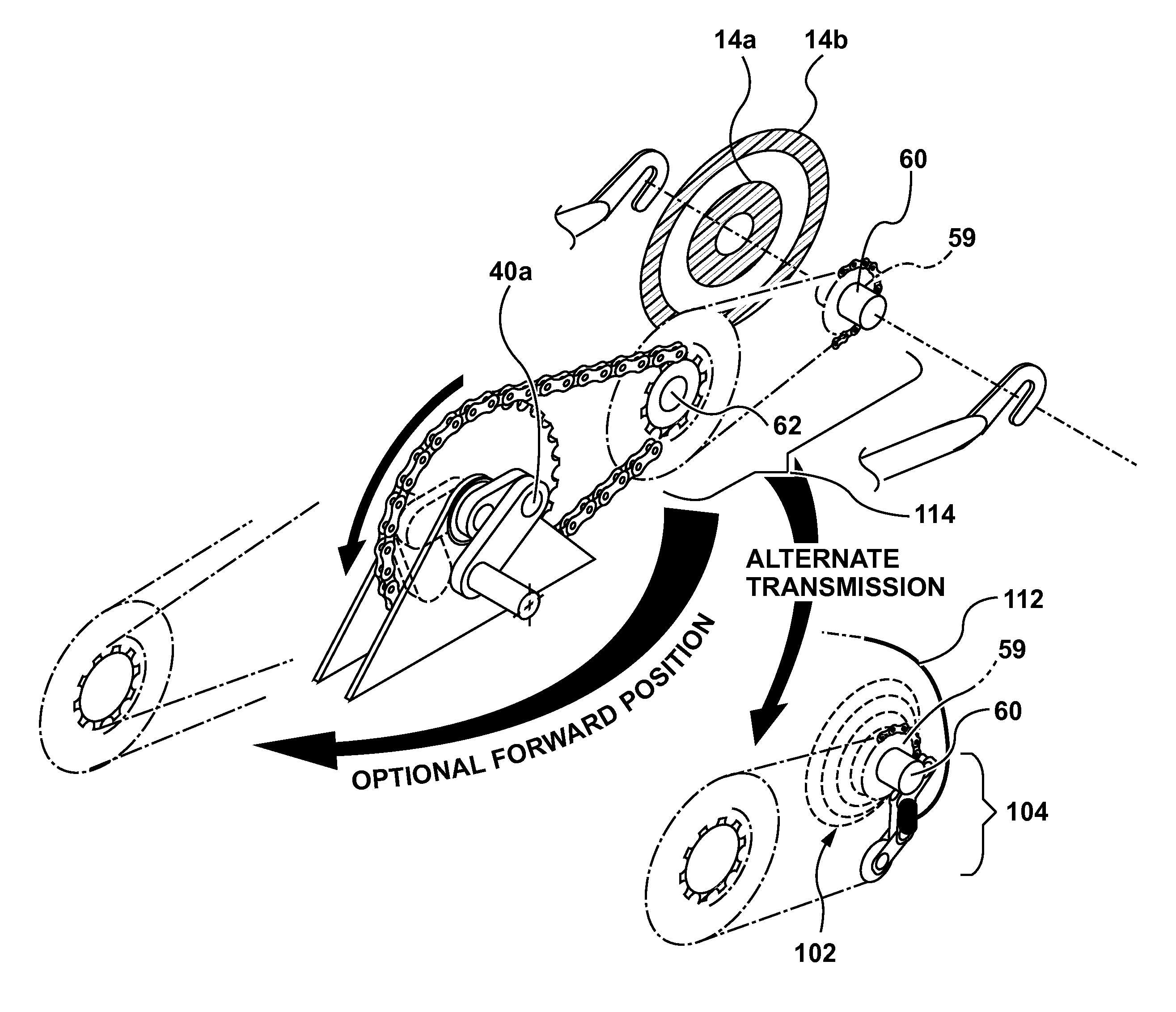
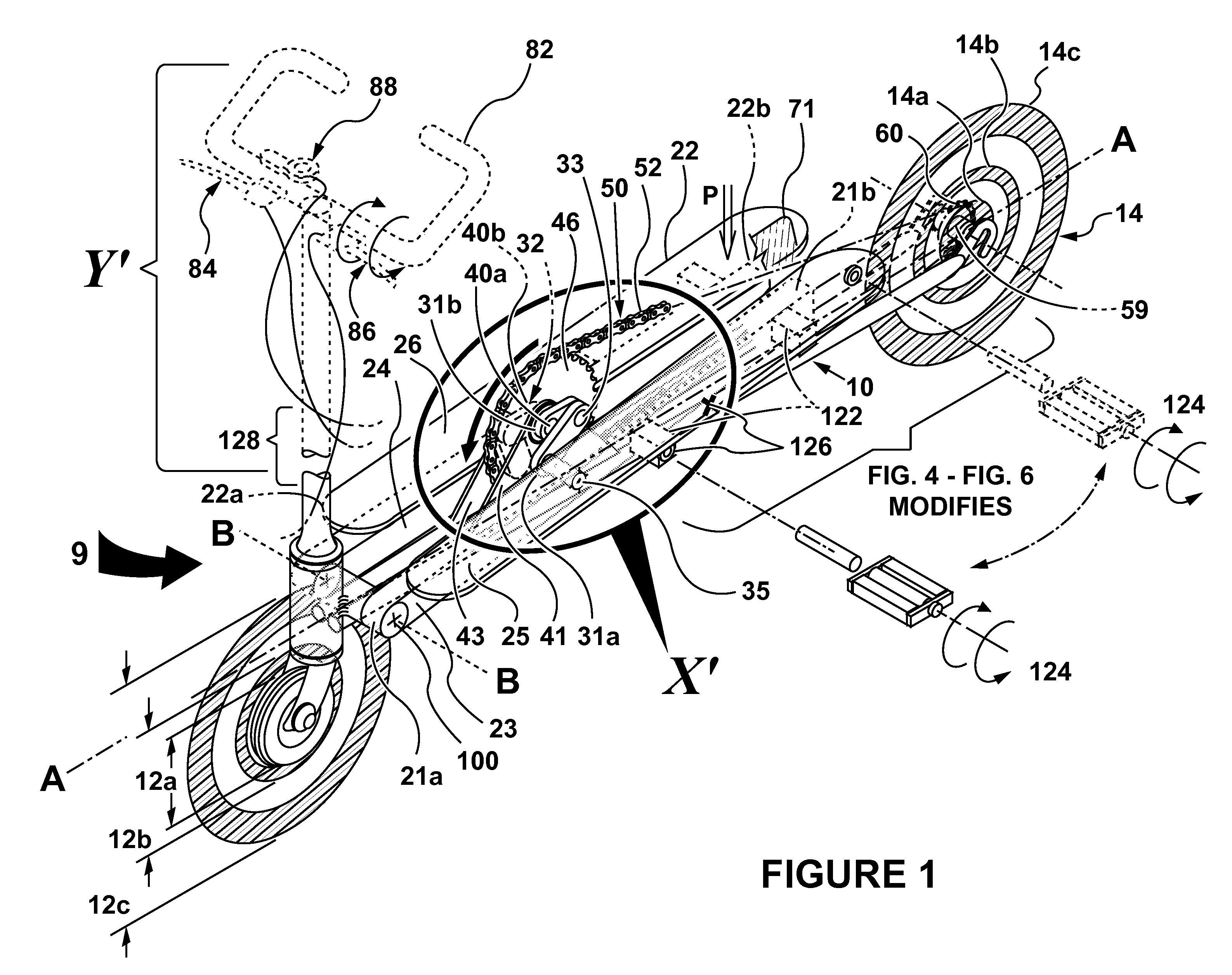
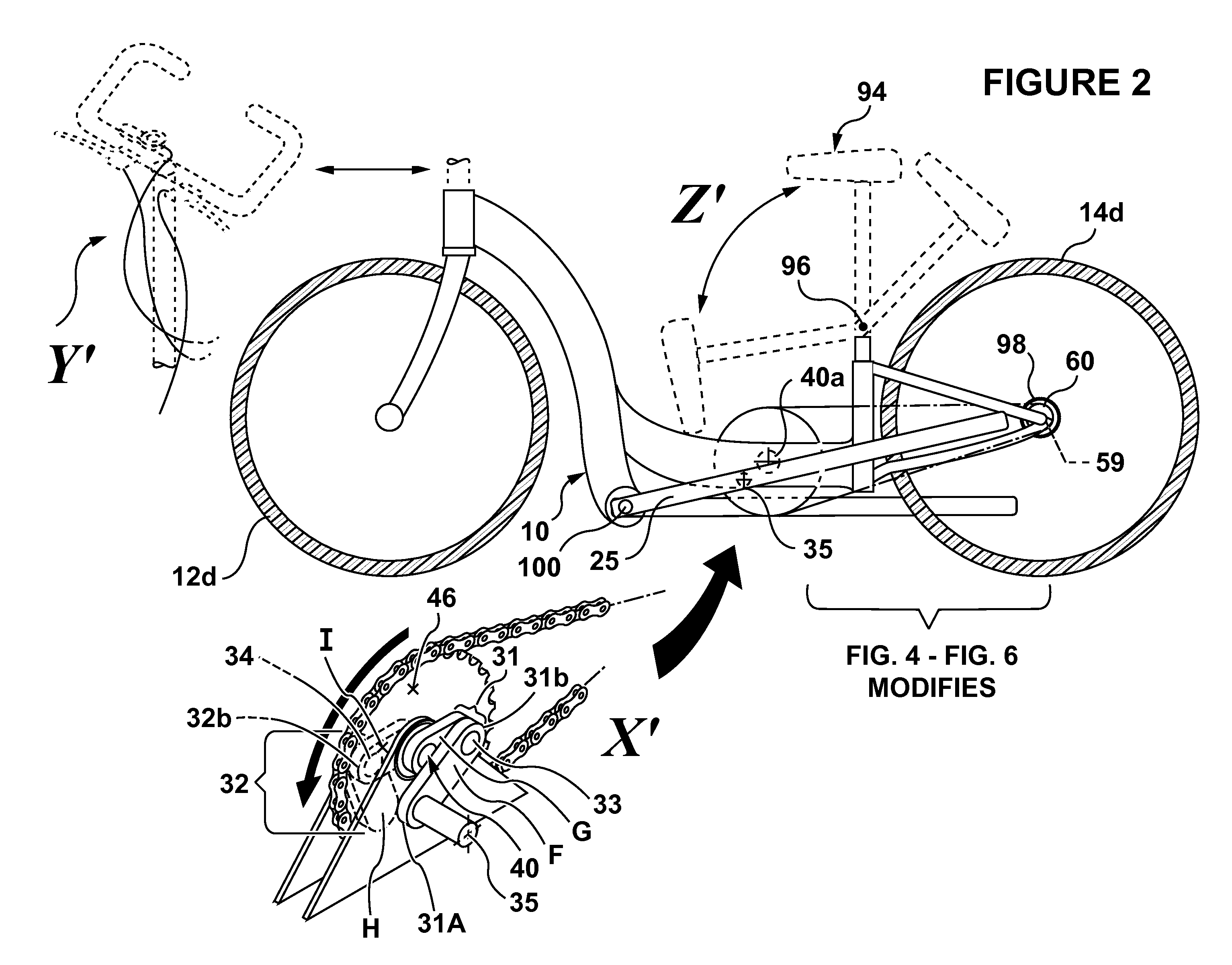
[0055]Noting FIG. 1 through FIG. 12, particularly FIG. 1 and FIG. 2, a pedal drive system 9 for propelling a multi-wheeled cycle is disclosed, comprising a handle assembly Y′ including a handle bar 82, possible handle hinge area 128 whereat or where near the area a hinge may be included, a first brake assembly 84, a second brake assembly 86 and a gear switch assembly 88. Note said drive system 9 having a hingable seat assembly Z′ including a seat 94, and a seat extension hinge 96. The said pedal drive system 9 further has a cycle frame 10 having frame axis A-A and proximal hinge axis B-B near the steera...


PUM


Abstract

A pedal-drive system for propelling multi-wheeled cycles includes two pedal level arms connected to a pair of two-bar linkages, which are drivingly attached to corresponding crank pins on each respective side of a common drive spindle, perpendicular to the cycle frame. The linkages rotate the said spindle per each pedal's downward stroke so that when one pedal arm is all the way down, the opposite pedal's crank pin is already beyond full up position, thus ensuring continuous rotation of the drive system. A sprocket on the spindle drives a chain, that drives a sprocket on a back wheel. For higher speeds, a typical bicycle multi-sprocket-cone and speed changing chain-derailleur may be incorporated. The pedal system may be used for small to large manually powered cycles, particularly scooters and bicycles, and may also include an auxiliary electric motor and battery for propulsion.

Description

BACKGROUND[0001]1. Field of the Invention[0002]Multi-wheeled cycles, or what is commonly known as scooters on the market today typically comprise a platform supported on a front wheel that may be steered by a solid fixed or foldable handle bar, and a back wheel, some including a dual rear wheel axle. The user propels the scooter by simply pushing one foot on the pavement or ground, providing driving thrust. Smaller versions of this standard of recent have become quite popular. However, there are many scooters, even in the early 20th century, that have attempted to put pedal driving means with this above arrangement as a more convenient alternative to the foot thrust drive, and manually power the scooter, instead, by pedal motive force. This pedal driving scooter, vehicle, is the field of the particular invention.[0003]2. Prior Art[0004]Many structures for scooters have been invented that propel the scooter using various drive systems, for example U.S. Pat. No. 4,186,934 describes a ...

Claims


Application Information

Patent Timeline
Patent Type & Authority Applications(United States)
IPC IPC(8): B62M1/04B62M1/24
CPCB62K3/002B62M2003/006B62M1/26
Inventor OWOC, GREGORY JOHNSCOLARI, NATHAN ANTHONY
Owner ZIKE
Why Eureka
Try Eureka