Switching power supply device and semiconductor device used for the same

Inactive Publication Date: 2011-03-10
COLLABO INNOVATIONS INC
View PDF10 Cites 13 Cited by
  • Summary
  • Abstract
  • Description
  • Claims
  • Application Information

AI Technical Summary

Benefits of technology

[0049]The semiconductor device thus configured can incorporate the switching element and the control circuit into a single package. Thus, by configuring the switching power supply device using the semiconductor device, the number of components of the switching power supply device can be significantly reduced, which allows reduction in size, weight and cost of the switching power supply device.
[0050]According to preferred embodiments of the present invention, it is not necessary to convert the output volt

Problems solved by technology

However, as the greater the required dielectric strength becomes, the capacitor increases in volume.
In addition, the cost of the capacitor also increases, which results in increasing the size and cost of the switching power supp

Method used


Image

  • Switching power supply device and semiconductor device used for the same
  • Switching power supply device and semiconductor device used for the same
  • Switching power supply device and semiconductor device used for the same

Examples


Example

Embodiment 1

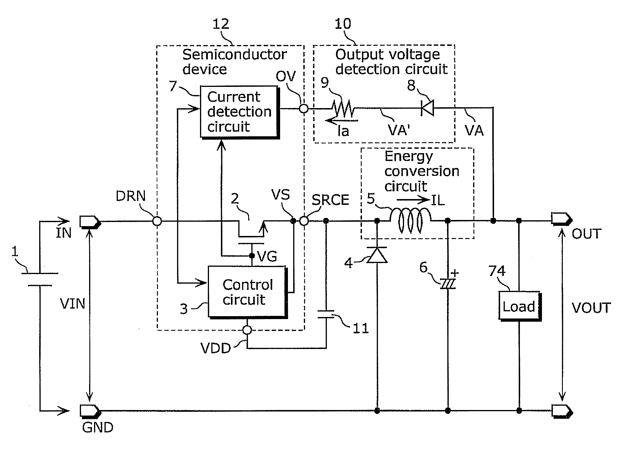
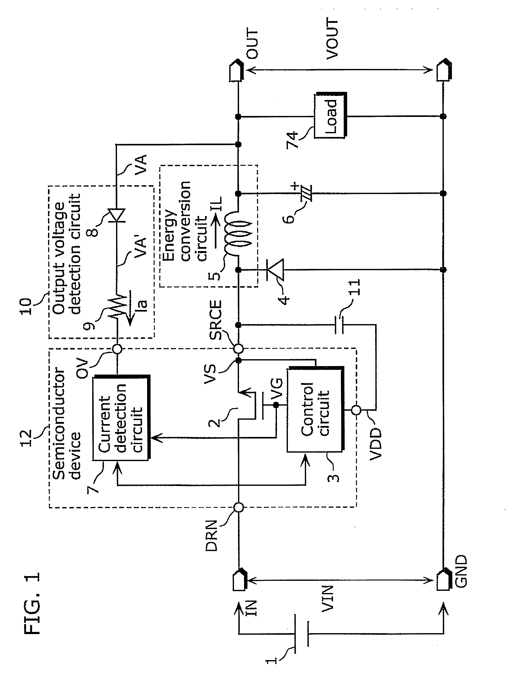
[0068]Embodiment 1 describes a configuration of a switching power supply device which converts an output voltage to a pulsating current, inputs the pulsating current to a current detection circuit, and detects current using the sampling current detection circuit. Since it is not necessary to convert the output voltage to the voltage smoothed relative to a reference voltage terminal of a control circuit, it is possible to achieve quick responsiveness to instantaneous changes in the output voltage and to reduce size and cost.

[0069]The switching power supply device achieves the above includes: an energy conversion circuit (for example, a coil) which converts the first DC voltage into a second DC voltage, the first DC voltage being switched by the switching element; a control circuit which outputs a driving signal for controlling an ON operation and an OFF operation of the switching element, using a voltage having an electric potential identical to an electric potential of a...

Example

Embodiment 2

[0111]Next, Embodiment 2 of the present invention is described. In Embodiment 2, a configuration is described in which the current detection circuit includes a blanking period generation circuit. The blanking period generation circuit sets, as a blanking period, a period in which a spike current can occur in the voltage-to-current conversion circuit. The current detection circuit prohibits current detection during a period from when the switching element is turned off until the blanking period ends. This suppresses false detection by the current detection circuit due to a noise current that occurs when the switching element is switched from its ON state to its OFF state.

[0112]FIG. 5 is a circuit diagram showing an example of a current detection circuit used for the switching power supply device and the semiconductor device according to Embodiment 2. In FIG. 5, like numerals are used to indicate like components in FIG. 3, and their descriptions are not repeated. The curre...

Example

Embodiment 3

[0121]Next, Embodiment 3 of the present invention is described. In Embodiment 3, a configuration of the control circuit is described which includes: a counter circuit which counts the number of times the first digital signal having a value of TRUE is input, and an overvoltage protection circuit which stops the switching operation of the switching element when the counter circuit counts the n times of input (where n is an integer of 1 or more) and holds the stopped state. With this, it is possible to count the number of times the output voltage instantaneously becomes equal to or above the detection voltage, thereby causing the overvoltage protection circuit to operate when the counted number of times reaches a predetermined number of times. By a user choosing an appropriate value for the detection sensitivity (that is, the number of counts) of the overvoltage protection circuit, it is possible to achieve a user-friendly overvoltage protection circuit.

[0122]FIG. 6 is a ci...


PUM


Abstract

In a switching power supply device in which an operation reference voltage of a control circuit has an electric potential identical to that of a connection point between a switching element and a coil that is an energy conversion circuit, an output voltage detection circuit includes: a rectification circuit which converts an output voltage into a voltage signal rectified relative to the operation reference voltage terminal of the control circuit; and a voltage-to-current converter which is connected between an input terminal of a current detection circuit and the rectification circuit, and which converts the rectified voltage signal into a current signal. The current detection circuit is a sampling type which detects a current by sampling the current signal applied to the input terminal of the current detection circuit.

Description

BACKGROUND OF THE INVENTION[0001](1) Field of the Invention[0002]The present invention relates to a switching power supply device and a semiconductor device used for the same.[0003](2) Description of the Related Art[0004]A buck converter is widely known as a step-down non-isolated switching power supply device which converts an input power supply voltage into a lower voltage and outputs the converted voltage.[0005]FIG. 13 shows an example of a general buck converter switching power supply device. Since the detailed operation of the buck converter is familiar to one skilled in the art, the following description focuses on aspects relevant to embodiments of the present invention. In FIG. 13, the voltage regulation of a direct current (DC) output terminal 114 relative to a power supply reference terminal 113 is determined by an output voltage detection circuit which includes a zener diode 112 and a photocoupler 110 and by an output voltage regulation circuit included in an integrated c...

Claims


Application Information

Patent Timeline
IPC IPC(8): G05F1/00
CPCH02M3/156
Inventor KUNIMATSU, TAKASHI
Owner COLLABO INNOVATIONS INC
Why Eureka
Try Eureka