
Low cost disposable medical forceps to enable a hollow central channel for various functionalities

a technology of medical forceps and hollow central channels, which is applied in the direction of surgical forceps, surgical staples, osteosynthesis devices, etc., can solve the problems of increasing the cost of such instruments, increasing the amount of play, and increasing the distortion of the jaw movement of the devi

Inactive Publication Date: 2011-03-10
TRUSTEES OF BOSTON UNIV +2
View PDF7 Cites 18 Cited by
  • Summary
  • Abstract
  • Description
  • Claims
  • Application Information

AI Technical Summary

Benefits of technology

[0006]The present invention provides a biopsy apparatus, in the form of forceps, graspers or other similar devices, for taking a tissue sample having one or two moving sections. The instabilities created by the multiple links and linkage assemblies of the prior art is reduced by elimination of many of the linkages and particularly the hinge pin as a separate member.

Problems solved by technology

The forceps conventionally used in such procedures utilize complex arrangements of linkage assemblies or cam type devices for articulating the jaws of the forceps.
As such instruments are of small size, such complexity results in complex machining and manufacturing procedures which greatly increase the cost of such instruments.
The multiple connections also increase the amount of play, which may increase the distortion of the movement of the jaws of the device.
Thus, present biopsy devices are generally very expensive and, the jaw actuating mechanisms are complex and may be inaccurate.
The small size and number of the linkages and hinge pins also decrease the durability of the biopsy forceps and increase their vulnerably to breakage.
This is an important consideration, especially when working within a patient where retrieval of a dissociated part may be difficult or dangerous to the patient.
Large numbers of small linkages and hinges also increase the cost and difficulty of manufacturing and assembly.
The sterilization and cleaning procedures will often decrease the performance or useful life span of the instrument, thereby magnifying the problem created by the complexity of manufacture and many parts which quickly wear.
Further, some devices which are intended only for single use still incorporate complex linkage or cam type devices for proper movement of the biopsy jaws.
This greatly inhibits their use as the costs associated with such instruments are normally still very high.

Method used


Image

  • Low cost disposable medical forceps to enable a hollow central channel for various functionalities
  • Low cost disposable medical forceps to enable a hollow central channel for various functionalities
  • Low cost disposable medical forceps to enable a hollow central channel for various functionalities

Examples


example 1

Side Hinge Concept

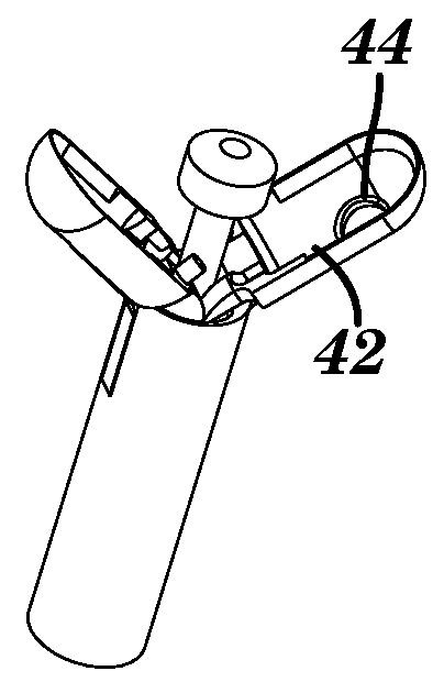
[0061]The hinges are offset from the center axis on the side of the tube, rather than in the middle as is done on conventional designs. This allows for maximal use of the internal space for additional functionalities. Furthermore, this design has the advantage of increased closing force as compared to the conventional mid-tube hinge design. See FIG. 21.

[0062]The length of the jaws “a” can be variable depending on the desired forces needed, and the length of “b” is limited by the tube size (See FIG. 22) in that the forceps can fit through the working channel of the medical scope. Here, the hinge sees an additional moment due to the twisting caused by asymmetric jaws. The hinge itself could be a pin hinge, a screw hinge with one or two screws, rivet, or any other equivalent attachment technique. The materials used for the hinge and jaws could be metal, plastic, or ceramic.

example 2

Ferrule Design

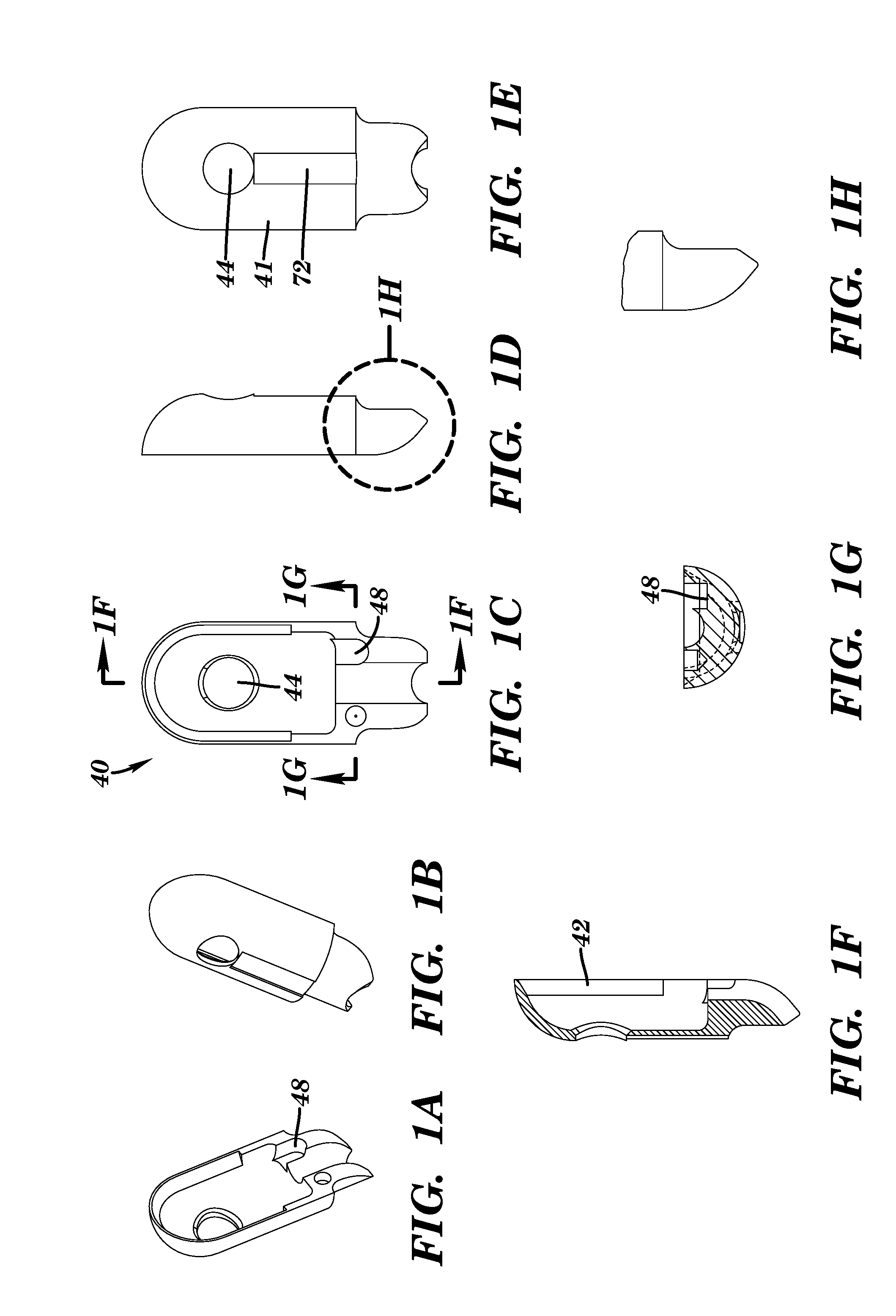
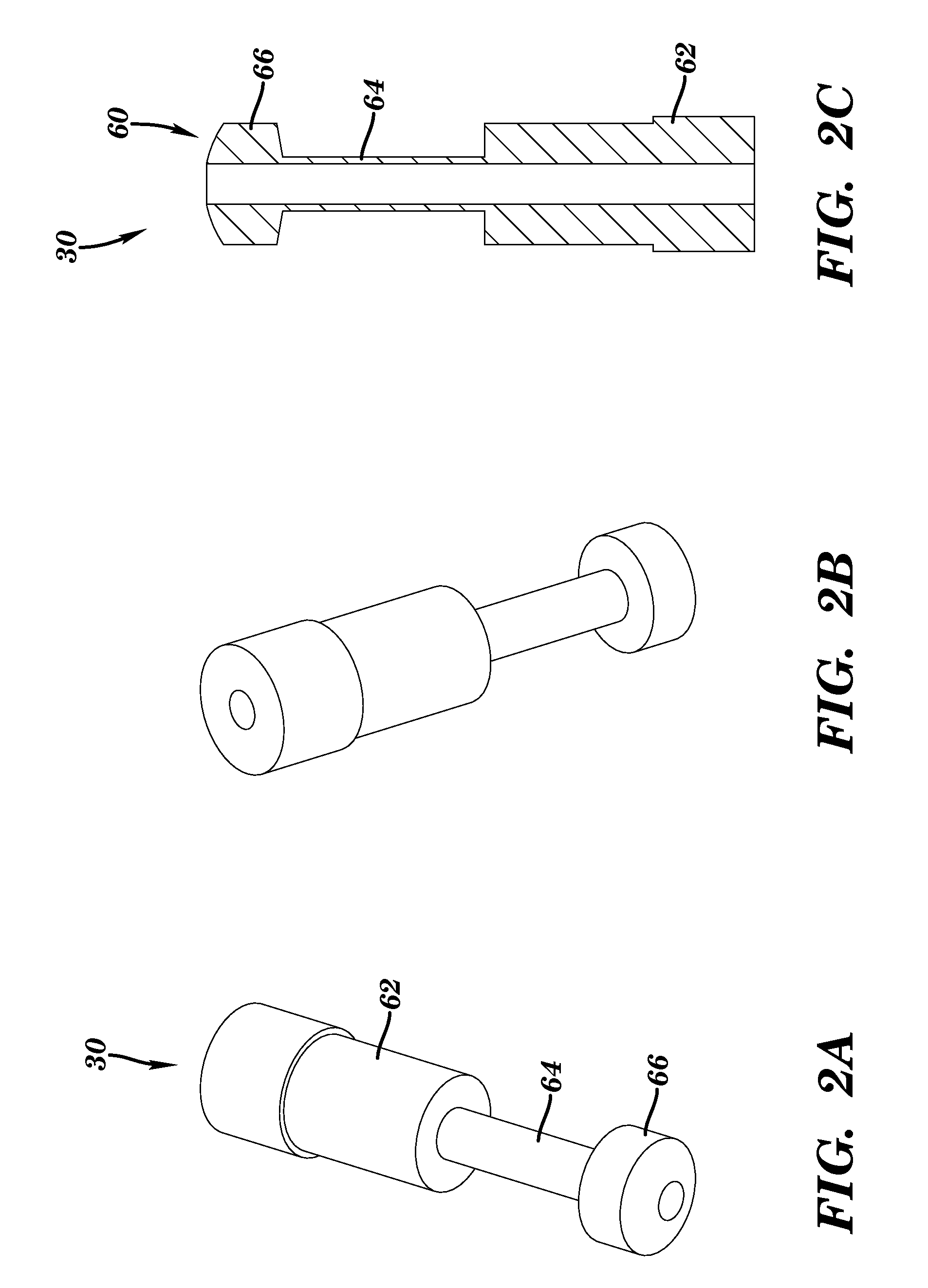
[0063]The jaws are opened and closed by using the CAM ferrule geometry (see FIGS. 7A-D). The ferrule is a rigid tube that contains the fiber-optics, and / or other components to provide additional functionalities to the forceps (see FIG. 5). The ferrule has physical features on the outside of the tube that mechanically open and close the forceps jaws. These features for example, could be rings or tabs which are a part of the ferrule or which are attached to the ferrule. The shape of the contact geometry (areas where ferrule comes in contact with the jaws) controls the opening and closing. The ferrule can be metal, plastic, and / or ceramic.

example 3

Flex Joint Concept This concept uses a flexible hinge to constrain the jaws (see FIG. 6). At least one flexible strip is needed for each jaw. Alternatively, the flexible hinge may be a sleeve. The flexible hinge extends from the tube to the jaw. The hinge can be attached between the tube and the jaw in a number of ways. For example, the strip can be a slot fit, welded, soldered, glued, melted, a single piece with the jaws or tube attached to the other member, etc. The strip material can be metal, plastic, textile, or made of any other flexible material. The jaws are actuated by the ferrule as described above. With this design, longer jaw arm geometry is possible which creates a higher closing force.


PUM


Abstract

The present invention relates to an endoscopic biopsy forceps (10) with an open central channel. The forceps include a sheath (20) having a proximal end and a distal end, a housing (50) connected with the distal end of the outer sheath, an open channel actuator control means (30) having a proximal end and a distal end and passing through the sheath, an operating means attached to the proximal end of the open channel actuator means, an open channel actuator (60.) attached to a distal end of the open channel actuator control means and having a first projection and second projection, a first jaw (40) having an actuator engagement projection and having a first position and a second position, and a second jaw having an actuator engagement projection and a first position and a second position. The first jaw and second jaw are movably connected to the housing, and when the open channel actuator is moved longitudinally along a body of the instrument, the first jaw moves between the open position and the closed position.

Description

CROSS REFERENCE TO RELATED APPLICATION[0001]This application claims benefit under 35 U.S.C. §119(e) of the U.S. Provisional Application No. 61 / 034,245 filed Mar. 6, 2008, the contents of which are incorporated herein by reference in its entirety.FIELD OF THE INVENTION[0002]The present invention relates to an endoscopic biopsy forceps with an open central channel that may be used as biopsy forceps, graspers, etc. with the additional capability of use with a central optical fiber or fiber bundle for concurrent optical measurements, such as elastic scattering spectroscopy, fluorescence spectroscopy, Raman spectroscopy, fluorescent microscopy, confocal microscopy, etc. The hollow open central channel is large enough to allow for further functionalities, including additional tooling such as a water port for cleaning, snare for cauterization, spike for collection of multiple biopsy samples or stabilization, vacuum, etc; while maintaining enough volume in the forceps cavity to obtain suffi...

Claims


Application Information

Patent Timeline
IPC IPC(8): A61B1/00A61B17/94A61B10/02
CPCA61B10/04A61B10/06A61B2017/22074A61B2017/2937A61B2017/00867A61B2019/5206A61B2019/5217A61B2017/00269A61B2017/294A61B2090/3614A61B2090/306
Inventor SHARON, ANDRESINGH, SATISHBIGIO, IRVINGATLADOTTIR, SVAVAFOSS, DOUGLASVOGTEL, PATRIK
Owner TRUSTEES OF BOSTON UNIV
Learn More