Microwave introducing mechanism, microwave plasma source and microwave plasma processing apparatus

a technology of plasma processing apparatus and introducing mechanism, which is applied in the direction of plasma technique, electric discharge lamps, particle separator tube details, etc., can solve the problems of difficult to have a stable microwave oscillation, short lifespan, and high equipment and maintenance costs, so as to shorten the moving range of slugs, reduce size, and thin thickness

Inactive Publication Date: 2011-03-17
TOKYO ELECTRON LTD
View PDF12 Cites 41 Cited by
  • Summary
  • Abstract
  • Description
  • Claims
  • Application Information

AI Technical Summary

Benefits of technology

[0026]In the first aspect of the present invention, the tuner including the pair of slugs made of a dielectric material, the slugs being movable along the inner conductor and the microwave transmission path being defined between the main body container and the inner conductor; the actuator for moving the slugs; and the controller for controlling the movement of the slugs is used as a slug tuner. Moreover, the controller controls the actuator to move both of the slugs together in the range of the ½ wavelength of the microwave while maintaining the same distance between the slugs and to move one of the slugs in the range of the ¼ wavelength of the microwave with regard to the other slug. Accordingly, it is possible to shorten a moving range of the slugs by a ¼ wavelength as compared with the conventional method, thereby allowing the microwave introducing mechanism to be scaled down. This contributes to the scaling-down of the microwave plasma source.
[0027]In the second aspect of the present invention, the tuner including the pair of slugs made of a dielectric material, the slugs being movable along the inner conductor and the microwave transmission path being defined between the main body container and the inner conductor; and the actuator for moving the slugs. Moreover, the slugs are made of the high-purity alumina. Since the high-purity alumina has a high dielectric constant, the slugs can be formed to have a thinner thickness than that of a slug made of quartz or resin and, thus, it is possible to scale down the microwave introducing mechanism by the reduced size. Further, due to the high dielectric constant, it is possible to widen the load matching range. Besides, since tan δ is small, this helps to reduce the amount of loss and degree of distortion in the microwave.
[0028]In the third aspect of the present invention, similar to the first aspect, the controller controls the actuator to move both of the slugs together in the range of the ½ wavelength of the microwave while maintaining the same distance between the slugs and to move one of the slugs in the range of the ¼ wavelength of the microwave with regard to the other slug. Then, as the microwave radiating antenna, the planar slot antenna in which four or more slots are uniformly formed is used. Accordingly, it is possible to shorten the moving range of the slugs by the ¼ wavelength as compared with the conventional method and to remove a mismatching portion near to the antenna. For that reasons, it is possible to scale down the microwave introducing mechanism much further. This contributes to the scaling-down of the microwave plasma source.
[0029]In the fourth aspect of the present invention, a pair of slugs is made of the high-purity alumina; the planar slot antenna in which four or more slots are uniformly formed is used as the microwave radiating antenna; and the controller controls the actuator to move both of the slugs together in the range of the ½ wavelength of the microwave while maintaining the same distance between the slugs and to move one of the slugs in the range of the ¼ wavelength of the microwave with regard to the other slug. Accordingly, the effects of the first aspect and the second aspect are mixed and, thus, it is possible to scale down the microwave introducing mechanism much further. This contributes to the scaling-down of the microwave plasma source.

Problems solved by technology

Since, however, the magnetron has a short lifespan of about half a year, the microwave introducing device using the magnetron has a drawback in which the cost for the equipment and the maintenance thereof is high.
For that reason, it is difficult to have a stable microwave oscillation.
However, the technique in the patent document 1 is disadvantageous in that an accurate impedance matching is required in a combiner; a large-sized isolator is required to transmit to the isolator itself the high-power microwaves outputted from the combiner; and it is difficult to adjust an output distribution of the microwave in the surface of the antenna.
The technique, however, is disadvantageous in that the apparatus becomes complicated because it is required that two or more large-sized stub tuners are installed in each of the divided channels and a mismatching portion is tuned.
Further, it is difficult to adjust the impedance of the mismatching portion with high accuracy.
However, such technique in the patent document 3 is disadvantageous due to the following reasons.
Besides, since a portion of ¼ wavelength around the antenna becomes a mismatching portion, it is difficult to use the portion to adjust the impedance.

Method used


Image

  • Microwave introducing mechanism, microwave plasma source and microwave plasma processing apparatus
  • Microwave introducing mechanism, microwave plasma source and microwave plasma processing apparatus
  • Microwave introducing mechanism, microwave plasma source and microwave plasma processing apparatus

Examples


Embodiment Construction

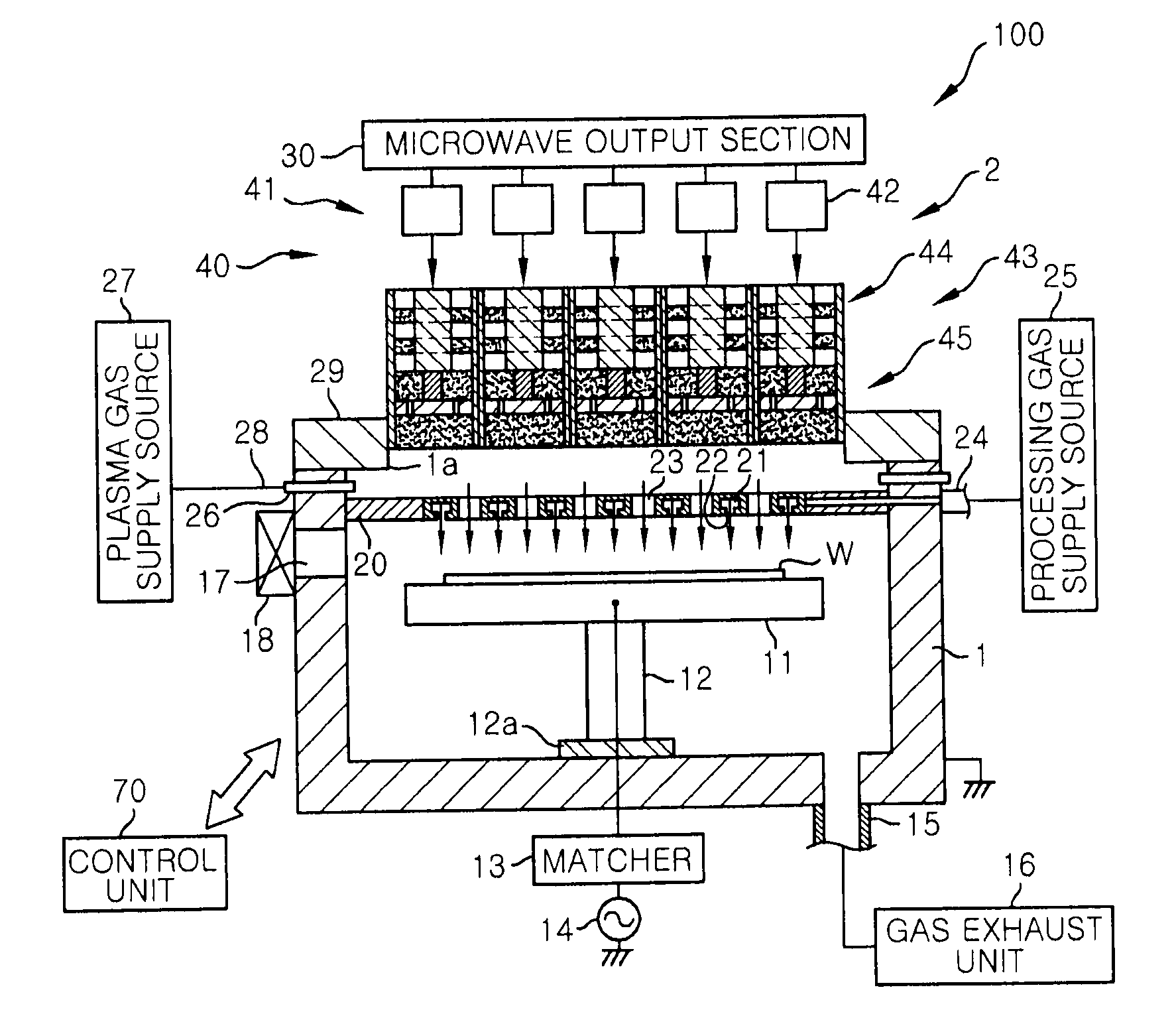
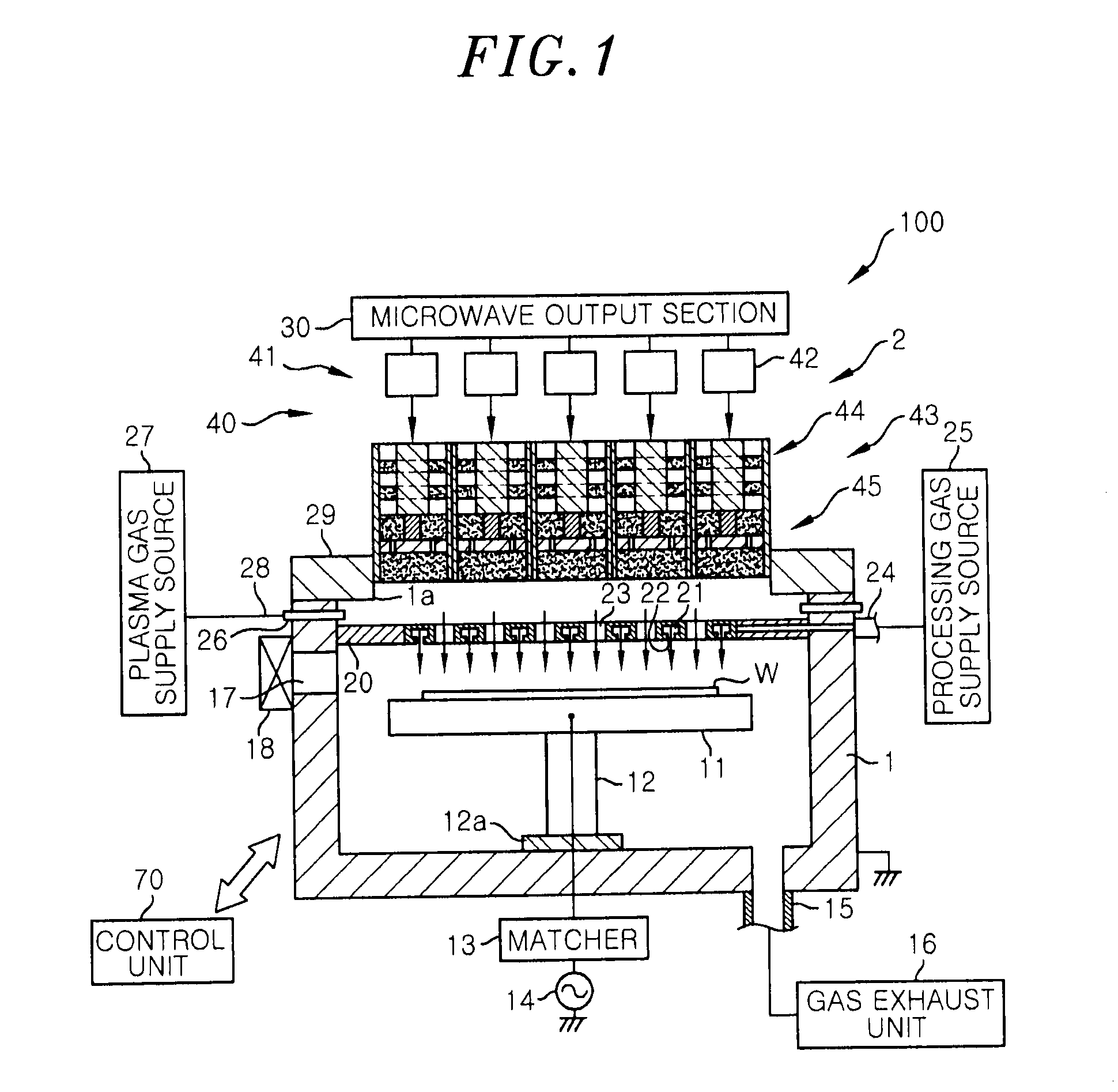
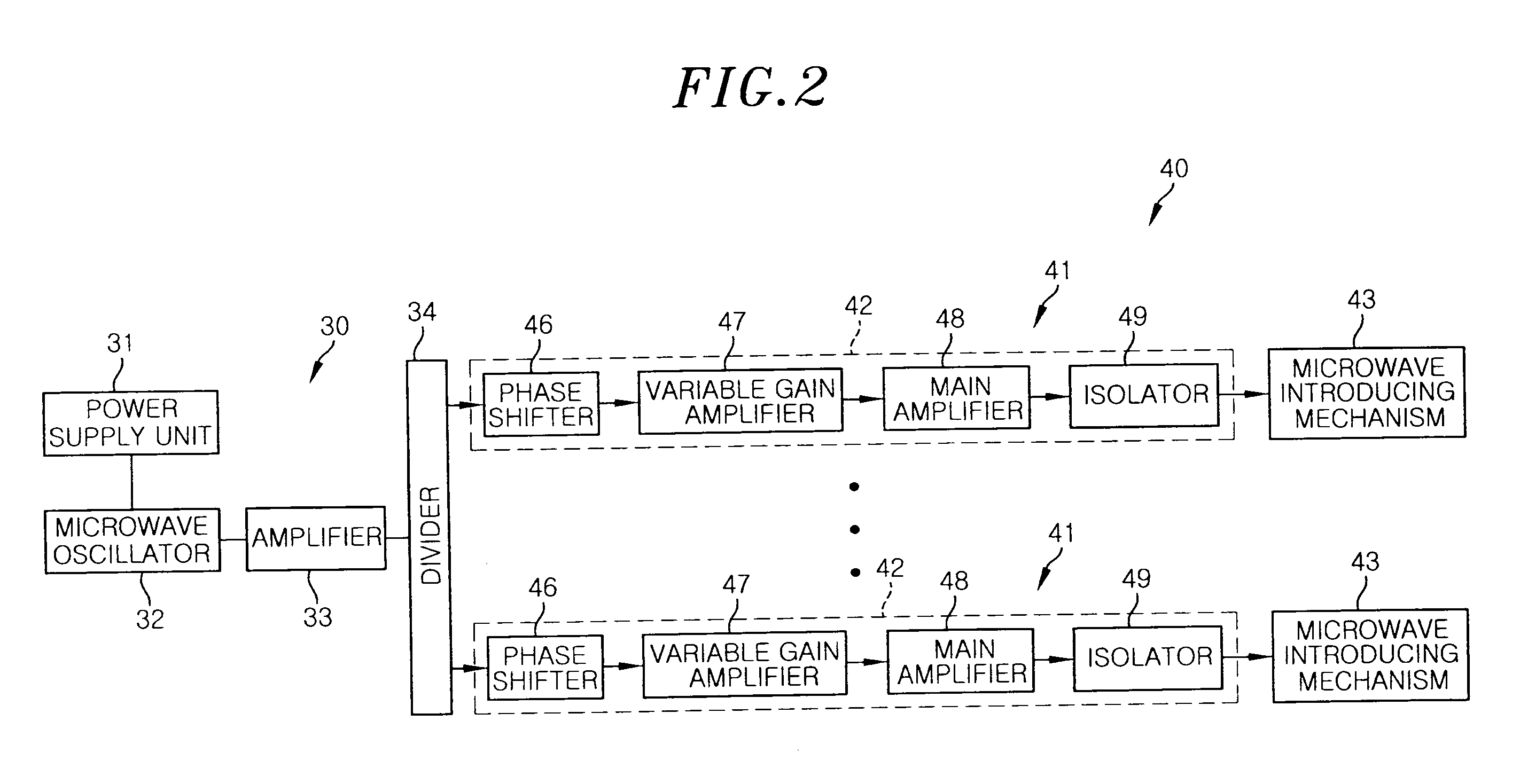
[0042]An embodiment of the present invention will now be described with reference to the accompanying drawings which form a part hereof. FIG. 1 is a cross sectional view showing a schematic configuration of a plasma processing apparatus including a microwave plasma source having a microwave introducing mechanism in accordance with an embodiment of the present invention, and FIG. 2 is a block diagram showing a configuration of the microwave plasma source shown in FIG. 1.

[0043]A plasma processing apparatus 100 is configured as a plasma etching apparatus for performing on a wafer a plasma process, e.g., an etching process. The plasma processing apparatus 100 includes a substantially cylindrical airtight chamber 1 that is grounded and made of a metal material such as aluminum, stainless steel or the like; and a microwave plasma source 2 for generating a microwave plasma in the chamber 1. An opening 1a is formed at an upper portion of the chamber 1, and the microwave plasma source 2 is p...


PUM

PropertyMeasurementUnit
frequencyaaaaaaaaaa
frequencyaaaaaaaaaa
frequencyaaaaaaaaaa

Abstract

A microwave introducing mechanism 43 includes a cylindrical container 50; an inner conductor 52, coaxially provided in the container 50, a microwave transmission path being defined between the container 50 and the inner conductor 52; a tuner 44 for adjusting an impedance of the microwave transmission path 53; and an antenna section 45 including an antenna 51 for radiating to the chamber a microwave transmitted through the microwave transmission path 53. The tuner 44 includes a pair of slugs 58 made of a dielectric material and movable along the inner conductor 52; an actuator 59 for moving the slugs 58; and a controller 60. The controller 60 controls both the slugs 58 to move together in a range of a ½ wavelength of the microwave and one of the slugs 58 to move in a range of a ¼ wavelength of the microwave with regard to the other slug.

Description

FIELD OF THE INVENTION[0001]The present invention relates to a microwave introducing mechanism for introducing a microwave into a chamber in which a plasma processing is performed, a microwave plasma source using the microwave introducing mechanism, and a microwave plasma processing apparatus using the microwave plasma source.BACKGROUND OF THE INVENTION[0002]In a process of manufacturing a semiconductor device or a liquid crystal display, a plasma processing apparatus such as a plasma etching apparatus and a plasma CVD film forming apparatus is employed to perform a plasma process such as an etching process or a film forming process on a target substrate to be processed such as a semiconductor wafer or a glass substrate.[0003]A few methods for generating a plasma in the plasma processing apparatus have been disclosed. According to one of the plasma generating methods, a plasma is generated with a capacitive coupling between parallel plate electrodes arranged in a chamber while a pro...

Claims


Application Information

Patent Timeline
Patent Type & Authority Applications(United States)
IPC IPC(8): H01L21/3065H01J37/32
CPCH01J37/32192H05H1/46H01J37/32256H01J37/3222
Inventor IKEDA, TARO
Owner TOKYO ELECTRON LTD
Why Eureka
Try Eureka