Membrane separation of water and fuel from engine oil in an internal combustion engine

a technology of engine oil and membrane, which is applied in the direction of membrane, lubricant mounting/connection, multi-stage water/sewage treatment, etc., can solve the problems of ejecting oil, accumulating water in oil, unburned fuel, etc., and achieves the effect of cleaning the relatively cold oil

Active Publication Date: 2011-03-17
GM GLOBAL TECH OPERATIONS LLC
View PDF8 Cites 17 Cited by
  • Summary
  • Abstract
  • Description
  • Claims
  • Application Information

AI Technical Summary

Benefits of technology

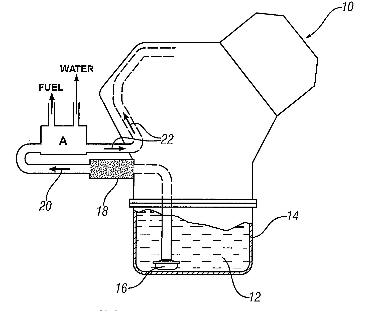
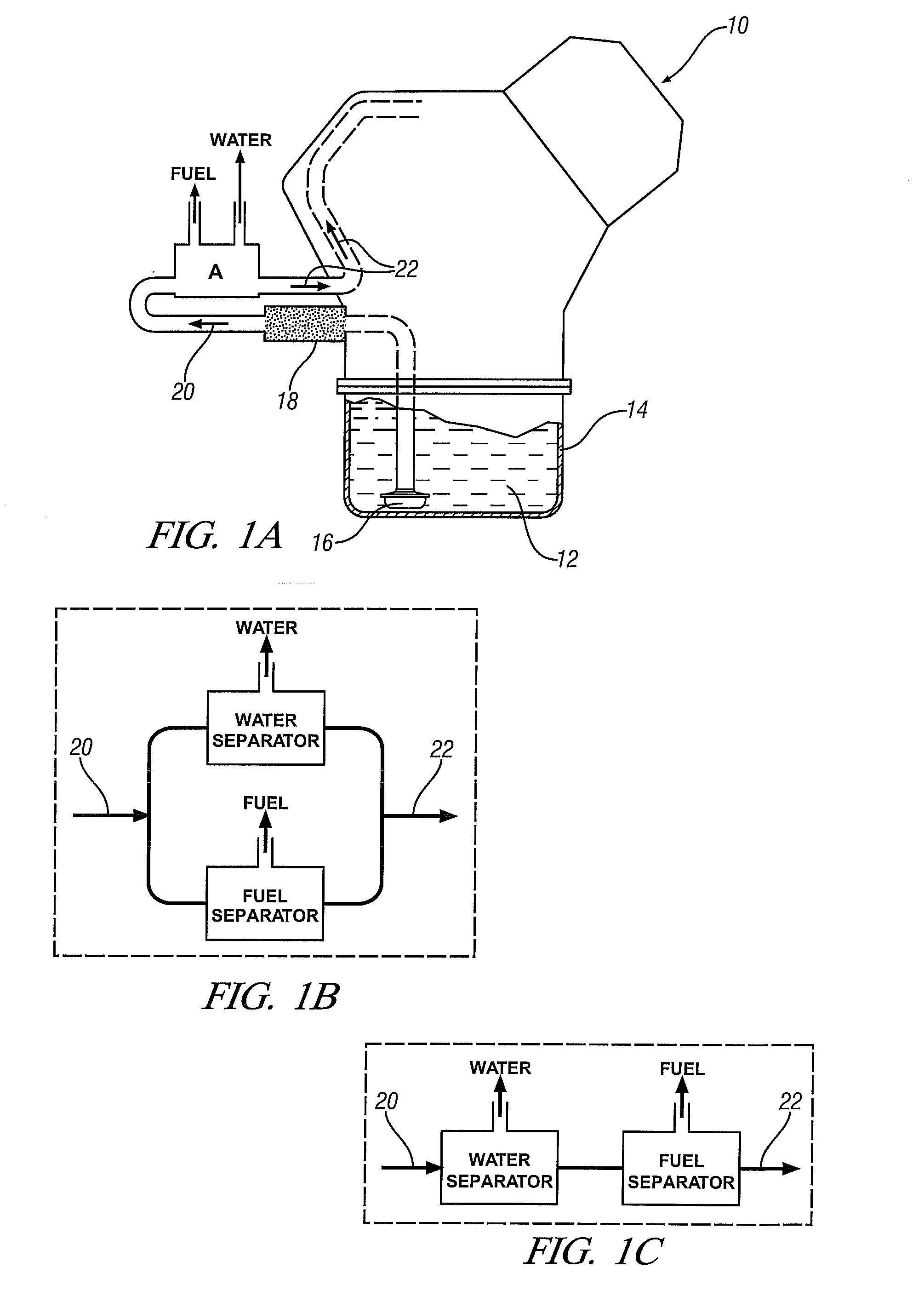
[0010]As stated above, the membrane structure of this invention is suitable for use in treating engine oil on a vehicle as the engine is operating. The membrane structure complements the function of an engine oil filter for removing particulate contaminants, and may, in some embodiments of the invention, be combined or associated with the filter. The membrane structure may be sized to treat only a portion of the circulating oil stream at any time. Air may be drawn from the engine compartment for carrying water and other permeate materials from the membrane assembly. In some embodiments of the invention, for example during short periods of engine operation, the oil may not be very hot but the membrane may be sized or otherwise adapted to cleanse the relatively cold oil.

Problems solved by technology

But the oil also accumulates water, un-burned fuel, and other liquid or gaseous combustion by-products which cannot be removed through conventional filtration techniques.
At normal engine operating temperatures these combustion by-products are often sufficiently volatile that they may be ejected from the oil by evaporation.
However when an engine is regularly operated for only relatively short periods, particularly at low ambient temperatures, the oil temperature does not increase sufficiently to vaporize and expel these contaminants and they progressively accumulate.
This accumulation of water, fuel, and combustion by-products, principally liquids, dilute and contaminate the oil such that it may have to be drained from the engine before its useful properties would have otherwise been depleted.

Method used


Image

  • Membrane separation of water and fuel from engine oil in an internal combustion engine
  • Membrane separation of water and fuel from engine oil in an internal combustion engine
  • Membrane separation of water and fuel from engine oil in an internal combustion engine

Examples


example

[0040]Cross-flow test modules in the design shown in FIG. 2 were fabricated using regenerated cellulose fiber obtained from Membrana / Celgard, Germany. The fibers had an inner diameter of 200 micrometers, a wall thickness of 8 micrometers, an effective pore diameter of 4-6 nanometers and a glass transition temperature of greater than 150° C. The test modules comprised a bundle of 300 fibers 16 cm long and the test mixture was continually circulated through the fibres at a flow rate of about 1.5 grams / minute under passage of sweep gas. At about 65° C., under an initial water content of 2.1 percent by weight an overall mass transfer coefficient of about 7.0×10⁻⁵ centimeters per second was observed. Further, increasing the oil flow indicated that further performance improvements were possible and an overall mass transfer coefficient of about 7.0×10⁻⁵ centimeters per second was observed at an oil flow rate of about 25 grams / minute.

[0041]The results described above were obtained using onl...


PUM


Abstract

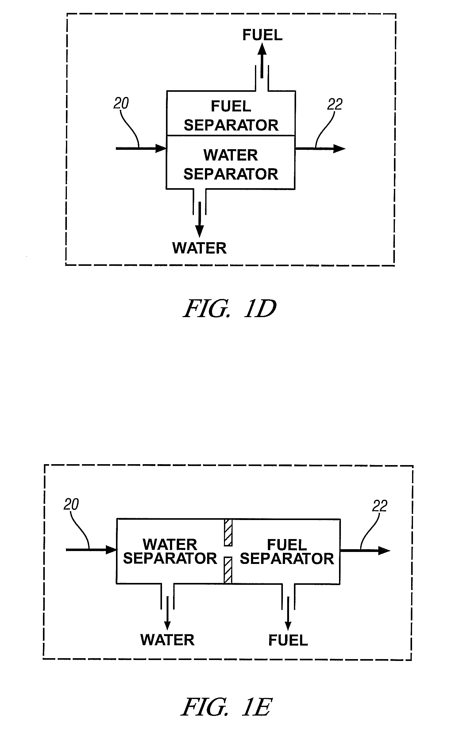
Water and fuel contaminating material may be removed from a stream operating engine. A suitable membrane material is supported in a suitable housing. At least a portion of the contaminated oil stream is flowed over one side of the membrane and water and fuel material diffuses through the membrane to its other side where they are gathered and removed from the housing. The water and fuel material may be recovered separately using different membranes or different regions of a membrane. They may be swept from the membrane and housing a flow of air for disposition outside the housing.

Description

TECHNICAL FIELD[0001]This disclosure pertains to methods and apparatus for separating water and gasoline (or other fuel) from lubricating oil that is circulating in an operating engine. More specifically, this disclosure pertains to methods for using apparatus in which oil is circulated along surfaces of membranes, and water and fuel constituents such as gasoline, diesel fuel or ethanol are selectively removed from the oil through the membranes. In general, the water and fuel constituents are removed in separate streams of flowing air from membrane surfaces.BACKGROUND OF THE INVENTION[0002]Most automotive vehicles are powered by internal combustion engines comprising several complementary cylinders in which closely fitting reciprocating pistons accommodate the introduction of a fuel-air mixture, the compression of the mixture, the combustion of the mixture, and the exhaust of combustion products. The fuel may be gasoline, diesel fuel, alcohol-fuel mixtures, alcohol, bio-fuel composi...

Claims


Application Information

Patent Timeline
Patent Type & Authority Applications(United States)
IPC IPC(8): B01D61/14
CPCB01D61/58B01D63/02B01D2311/13B01D63/082B01D63/10B01D63/06
Inventor MORDUKHOVICH, GREGORYMANCE, ANDREW M.
Owner GM GLOBAL TECH OPERATIONS LLC
Why Eureka
Try Eureka