Molded motor

Active Publication Date: 2011-03-24
FUJITSU GENERAL LTD
View PDF10 Cites 11 Cited by
  • Summary
  • Abstract
  • Description
  • Claims
  • Application Information

AI Technical Summary

Benefits of technology

[0020]According to this configuration, since the holding member is formed along the axis line direction of the stator core, and the holding groove for holding the conducti

Problems solved by technology

If this voltage is higher than the voltage allowed against the insulation resistance of bearing grease, electric discharge takes place on the bearing rolling surface, so that the bearing may be damaged by the electric discharge machining effect.
The occurrence of electrolytic corrosion produces flaking, pitting, fluting (wash

Method used


Image

  • Molded motor
  • Molded motor
  • Molded motor

Examples


Embodiment Construction

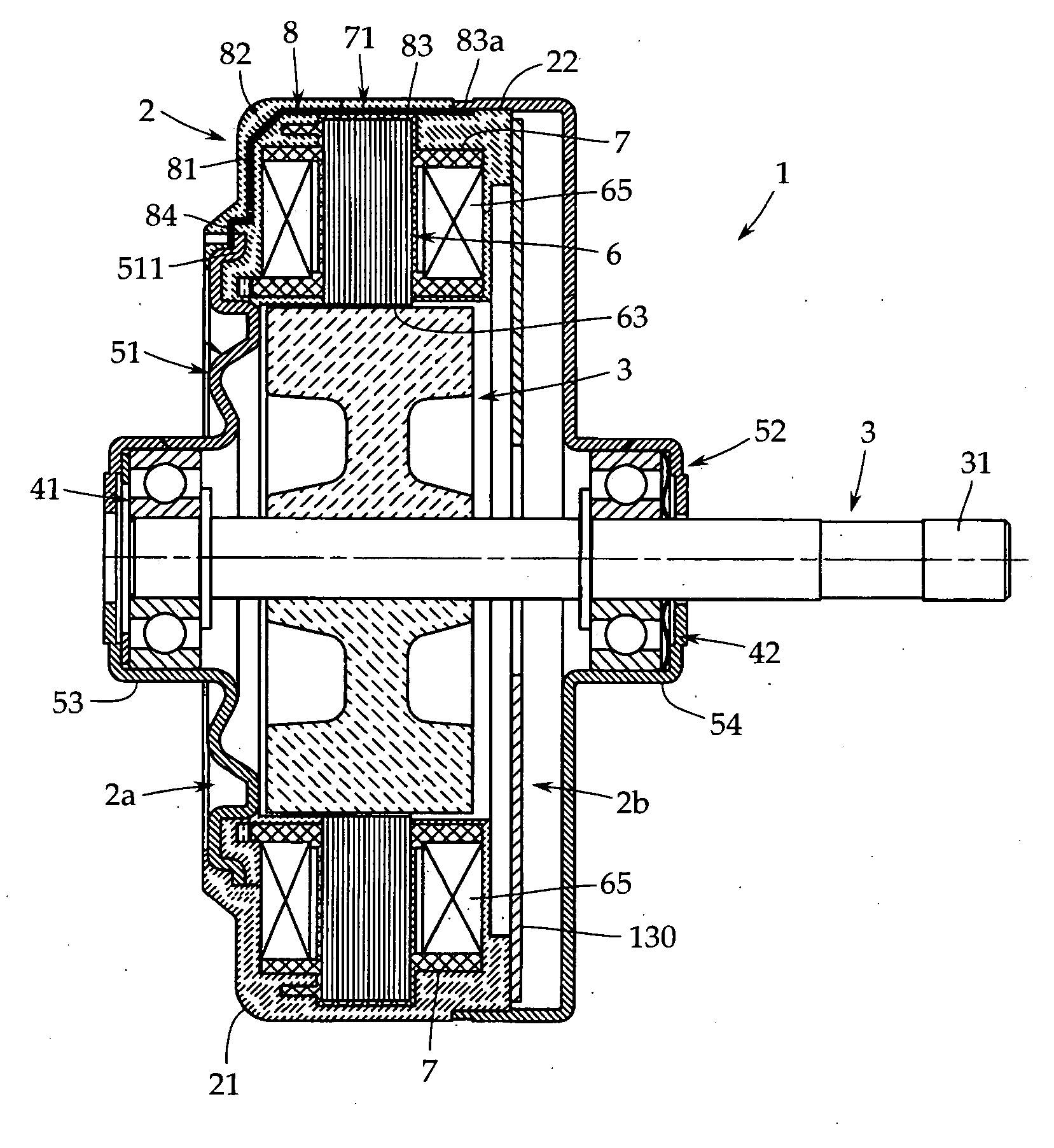
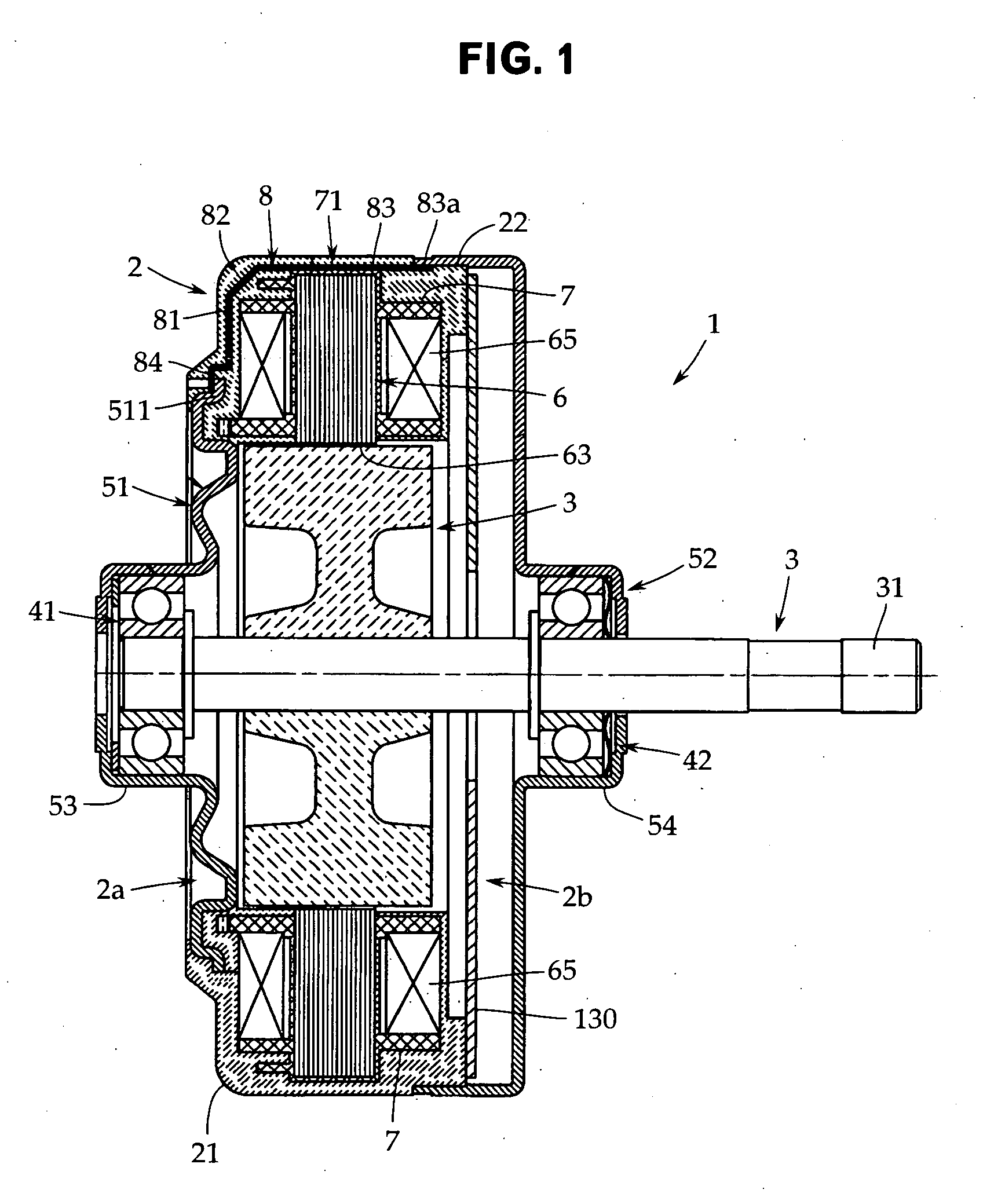
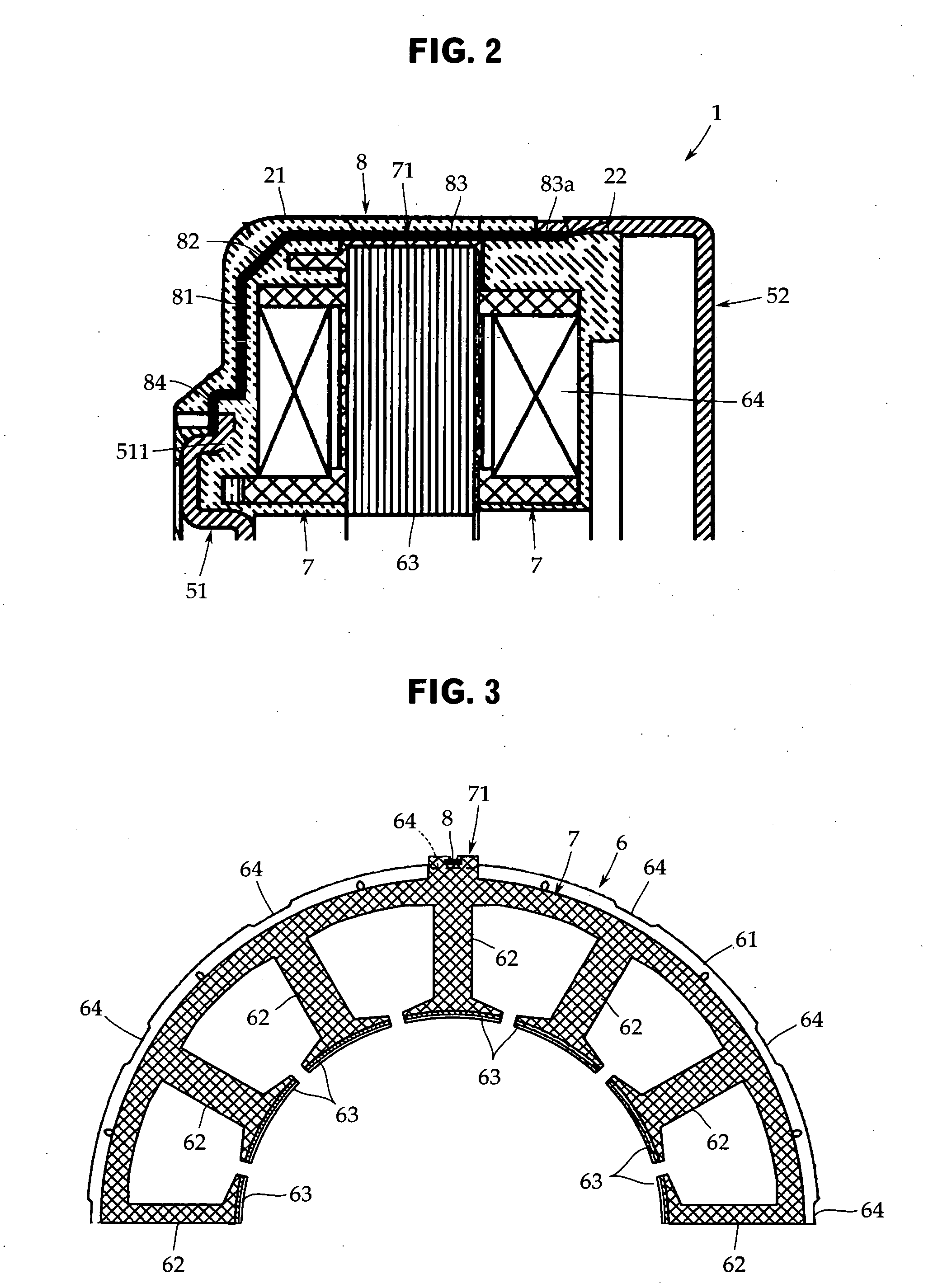
[0035]An embodiment of the present invention will now be described with reference to the accompanying drawings. The present invention is not limited to this embodiment. As shown in FIG. 1, an electric motor 1 includes a stator 2 and a rotor 3. The stator 2 is configured so that a stator core 6 configured by laminating magnetic steel sheets each blanked into a ring shape is molded integrally by a molding resin with the inner peripheral surface (a teeth surface 63) thereof being left, and is covered with a molding resin part 21. The rotor 3 is arranged on the inner periphery side of the stator 2 so as to face to the teeth surface 63 of the stator 2.

[0036]On both the end surface sides in the axial direction (on the left-hand surface side and the right-hand surface side in FIG. 1) of the stator 2, a pair of bearings 41 and 42 for rotatably supporting an output shaft 31 of the rotor 3 and a pair of brackets 51 and 52 for holding the bearings 41 and 42, respectively, are provided.

[0037]On...


PUM


Abstract

To prevent electrolytic corrosion from occurring by reliably establishing an electrical conduction between a motor output shaft and brackets. A first bracket 51 attached to one end part and a second bracket 52 attached to the other end part are electrically connected to each other via a conductive member 8 embedded in a molding resin part 21 of a stator 2.

Description

CROSS-REFERENCE TO RELATED APPLICATIONS[0001]The present application is based on, and claims priority from, Japanese Application Serial Number JP2009-217713, filed Sep. 18, 2009, the disclosure of which is hereby incorporated by reference herein in its entirety.TECHNICAL FIELD[0002]The present invention relates to a molded motor in which the whole of a stator is molded integrally by using a molding resin. More particularly, it relates to a grounding structure of molded motor for preventing electrolytic corrosion.BACKGROUND ART[0003]For example, as described in Japanese Patent Application Publication No. 2007-20348, in an inverter-controlled brushless DC motor, a minute voltage is induced between the output shaft and the frame of the motor. If this voltage is higher than the voltage allowed against the insulation resistance of bearing grease, electric discharge takes place on the bearing rolling surface, so that the bearing may be damaged by the electric discharge machining effect. T...

Claims


Application Information

Patent Timeline
IPC IPC(8): H02K11/00
CPCH02K5/02H02K11/0089H02K5/1732H02K3/325H02K11/40
Inventor TERAKUBO, HIDETAKAYAMADA, TOSHIHIKOMORI, TAKAOKI
Owner FUJITSU GENERAL LTD
Why Eureka
Try Eureka